Earth-penetrating radar with inherent near-field rejection

a radar and near-field technology, applied in the field of ground penetrating radars, can solve the problems of burying the antenna or contacting the surface, burying the echo signals deep in the noise floor, and affecting the accuracy of earth-penetrating imaging, so as to achieve the effect of increasing the gain and efficient earth-penetrating imaging

Inactive Publication Date: 2009-07-02
STOLAR
View PDF5 Cites 17 Cited by
  • Summary
  • Abstract
  • Description
  • Claims
  • Application Information

AI Technical Summary

Benefits of technology

[0008]An advantage of the present invention is that a radar is provided for efficient earth-penetrating imaging.
[0009]Another advantage of the present invention is that a ground-penetrating radar is provided that allows gain to be increased because unwanted signals from near reflections are zeroed out in demodulation.

Problems solved by technology

Unfortunately for earth penetrating radars, a big echo reflection occurs at the adjacent interface of air and earth.
Burying the antenna or contacting the surface are very often not practical.
But all these suffer from strong reflections at the ground that can swamp the receiver and bury the echo signals deep in the noise floor.

Method used


Image

  • Earth-penetrating radar with inherent near-field rejection
  • Earth-penetrating radar with inherent near-field rejection
  • Earth-penetrating radar with inherent near-field rejection

Examples


Embodiment Construction

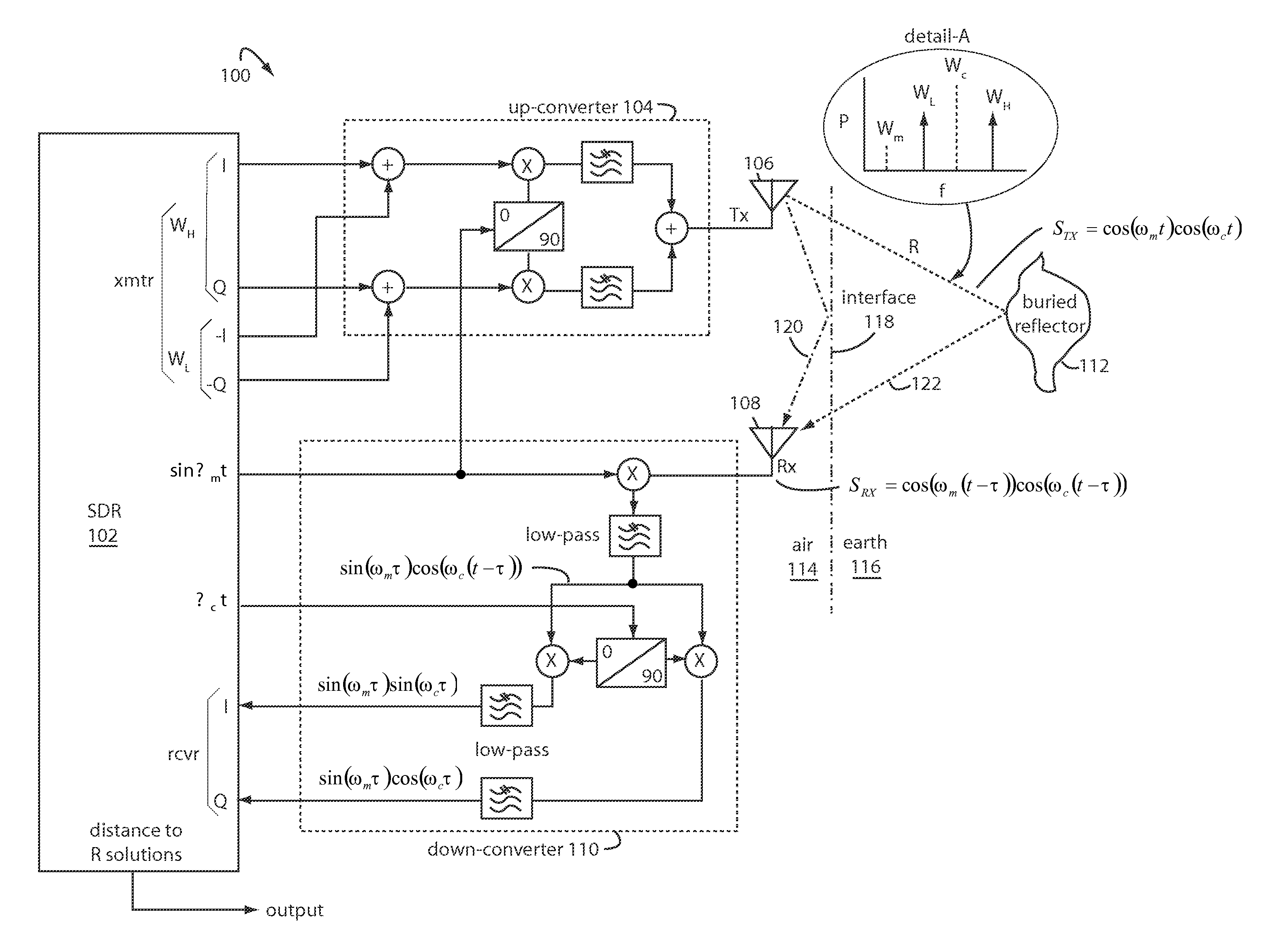
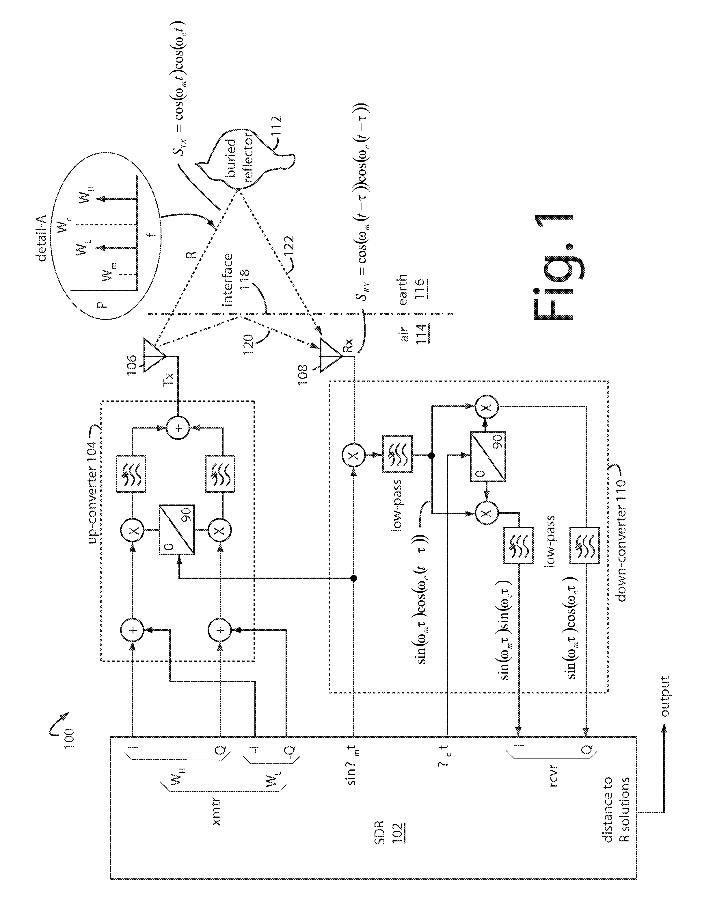
[0014]FIG. 1 illustrates a radar embodiment of the present invention, and is referred to herein by the general reference numeral 100. The challenges in design are two fold, how to generate widely separated coherent frequencies, and how to transmit the two widely separated signals with equal amplitudes. Radar 100 does both by using software defined radio (SDR) techniques to generate the two coherent baseband frequencies separated by 1 MHz, and then uses up-conversion to increase the separation to 30 MHz. This technique also makes it practical to use the current state-of-the-art SDR technology, since clock frequencies are limited to well below the 30 MHz carrier frequencies used here. Adaptive digital predistortion techniques are used to equalize the magnitudes of the two frequencies by using feedback to calibrate for the compensation needed. Such then eliminates the expense of using low distortion power amplifiers and flat frequency response antennas.

[0015]The radar 100 comprises a s...


PUM


Abstract

A ground-penetrating radar comprises a transmitter for launching pairs of widely separated and coherent continuous waves. Each pair is separated by a different amount, such as 10 MHz, 20 MHz, and 30 MHz. These are equivalent to modulation that have a phase range that starts at 0-degrees at the transmitter antenna which is near the ground surface. Deep reflectors at 90-degrees and 270-degrees will be illuminated with modulation signal peaks. Quadrature detection, mixing, and down-conversion result in 0-degree and 180-degree reflections effectively dropping out in demodulation.

Description

FIELD OF THE INVENTION[0001]The present invention relates to ground penetrating radars, and more particularly to radars that are able to completely suppress media interface reflections occurring very close at the air-ground interface.DESCRIPTION OF THE PRIOR ART[0002]Earth-penetrating radars have been studied and applied by Stolar Horizon (Raton, N. Mex.) to coal mining and automated mining safety devices. Conventional radars typically send out a radio pulse, and an echo will typically be returned by any objects with a contrast in their dielectric constant values. The time the echo takes to return is proportional to the distance the objects are from the radar antenna. Unfortunately for earth penetrating radars, a big echo reflection occurs at the adjacent interface of air and earth. The echo can be strong enough to swamp the echoes returning from deeper, smaller objects of interest. Burying the antenna or contacting the surface are very often not practical.[0003]Frequency sweeping r...

Claims


Application Information

Patent Timeline
Patent Type & Authority Applications(United States)
IPC IPC(8): G01S13/88
CPCG01S13/32G01V3/12G01S13/89G01S13/885
Inventor BAUSOV, IGOR
Owner STOLAR
Why Eureka
Try Eureka