Image display device

Inactive Publication Date: 2009-07-02
SHARP KK
View PDF13 Cites 85 Cited by
  • Summary
  • Abstract
  • Description
  • Claims
  • Application Information

AI Technical Summary

Benefits of technology

[0033]This makes it possible to perform luminance control according to the characteristics of each image because, in such a way, on the basis of the image characteristic values obtained by weighting the results of the histogram determination and thereafter taking averages thereof, it is possible to distinguish even images which are indistinguishable from each other on the basis of the average luminance levels (APL) thereof, such as the image consisting of the darkest half-screen part and the brightest half-s

Problems solved by technology

There is a problem that the luminance control which is appropriate enough to the characteristics of the image cannot be performed in conventional arrangements such that the backlight is controlled in accordance with the average luminance level of the video signal, as described in the patent do

Method used


Image

  • Image display device
  • Image display device
  • Image display device

Examples


embodiment 1

[0066]An image display device of Embodiment 1 of the present invention is described with reference to FIGS. 1 through 10, 11(a), 11(b), and 11(c).

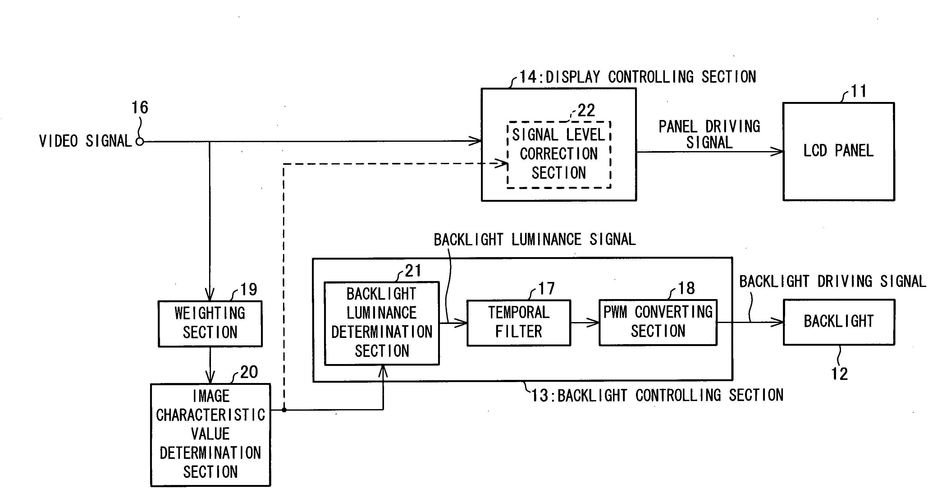
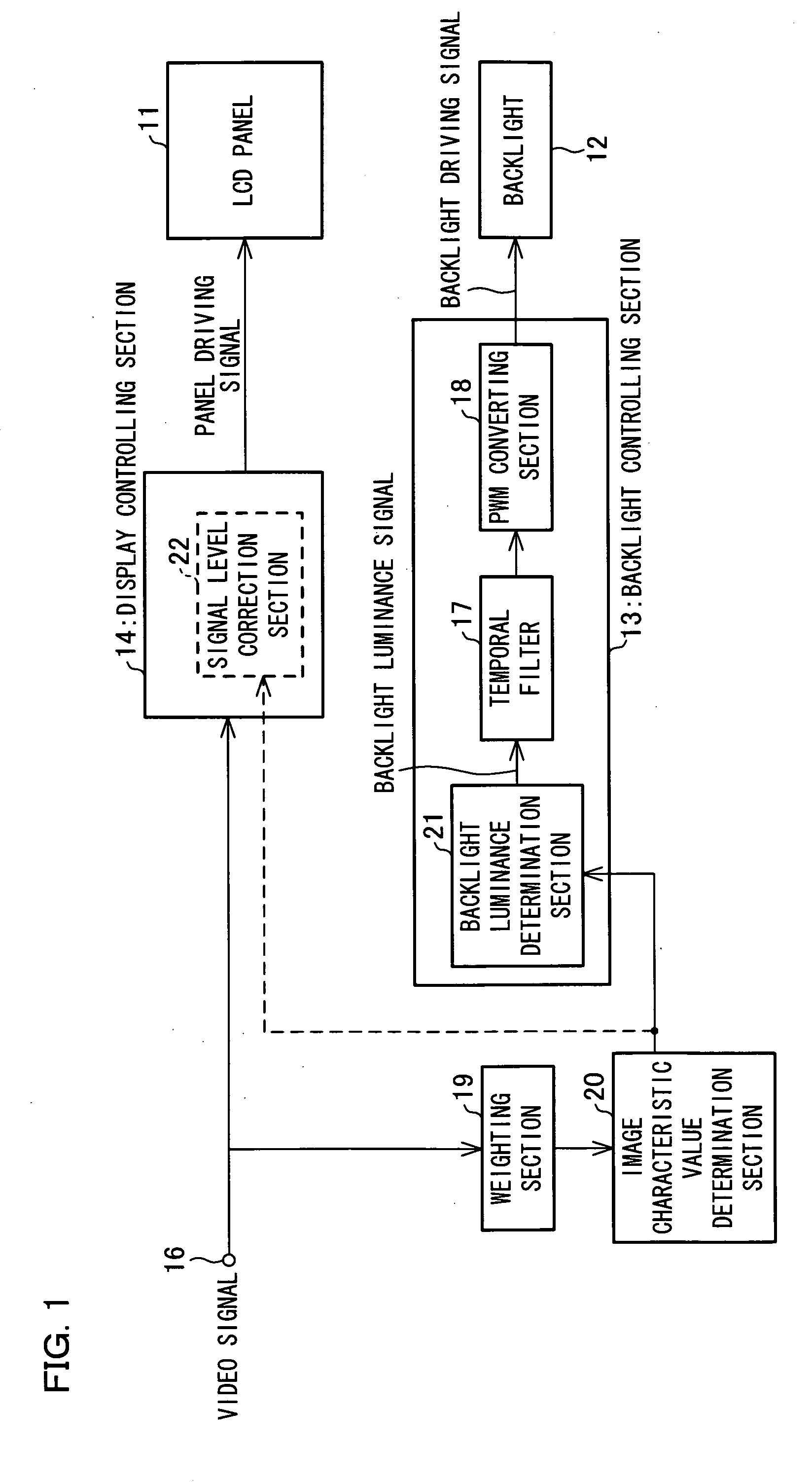
[0067]FIG. 1 is a block diagram illustrating a structure of the image display device of Embodiment 1 of the present invention. As illustrated in FIG. 1, the image display device includes an LCD panel (a light modulation device) 11, a backlight (a light source) 12, a backlight controlling section (a light source controlling section) 13, a display controlling section 14, a weighting section (a weighting means) 19, an image characteristic value determination section (an image characteristic value determining means) 20, and an input 16.

[0068]A video signal to be displayed on the LCD panel 11 is inputted from the input 16 in the form of, for example, a YPbPr signal. The display controlling section 14 performs control in order to display the video signal on the LCD panel 11 and outputs the video signal to the LCD panel 11 as a panel driving sign...

embodiment 2

[0110]An image display device of Embodiment 2 of the present invention is described below with reference to FIGS. 12 and 13. For the sake of simplicity, members with same functions as those of members of Embodiment 1 are given the same symbols and descriptions for the members are omitted.

[0111]FIG. 12 is a block diagram of a structure of the image display device of Embodiment 2 of the present invention. As illustrated in FIG. 12, the image display device additionally includes a luminance sensor 23 whose measurement output is inputted into a backlight luminance determination section 21′ in a backlight controlling section 13′. The backlight controlling section13′ is different from the backlight controlling section 13 only in that the backlight controlling section 13′ includes the backlight luminance determination section 21′ instead of the backlight luminance determination section 21.

[0112]The luminance sensor 23 is for the measurement of luminance around the image display device. A m...

embodiment 3

[0118]An image display device of Embodiment 3 of the present invention is described below with reference to FIGS. 14 through 16, FIG. 17(a), and FIG. 17(b). For the sake of simplicity, members with same functions as those of members of Embodiments 1 and 2 are given the same symbols and descriptions for the members are omitted.

[0119]FIG. 14 is a block diagram of a structure of the image display device of Embodiment 3 of the present invention. As in FIG. 14, the image display device additionally includes a histogram determination section (a means for determining histograms) 26. A histogram determination output determined by the histogram determination section 26 is inputted into the weighting section 19.

[0120]The histogram determination section 26 is for dividing luminance information of one frame of an input video signal (a pixel value) into a plurality of luminance information classifications and determining histogram distribution corresponding to each luminance information classifi...


PUM


Abstract

In one embodiment of the present invention, luminance information of a video signal inputted thereto is weighted by a weighting section. An image characteristic value determination section, by one frame, takes an average of the weighted luminance information, thereby determining an image characteristic value of one frame. A backlight controlling section sets luminance of the backlight at a backlight luminance determination section in accordance with the image characteristic value determined by the image characteristic value determination section and performs luminance correction.

Description

TECHNICAL FIELD[0001]The present invention relates to a display device, in particular, an image display device including a light source and a light modulation device for changing luminance of a display image by attenuating light from the light source in accordance with a video signal.BACKGROUND ART[0002]Some liquid crystal image display devices have been configured as transmission-type image display devices having light source means. The transmission-type image display device requires a light source because the liquid crystal panel (the light modulation device) thereof is that of a non-emissive type, i.e., the liquid crystal panel itself does not illuminate. A direct-view-type liquid crystal image display device is provided with a light irradiation section called a backlight behind the liquid crystal panel thereof. A fluorescent tube called a cold-cathode tube is generally used as a light source. A projective-type liquid crystal image display device, popularly termed a liquid crysta...

Claims


Application Information

Patent Timeline
IPC IPC(8): G09G3/36
CPCG09G3/3406G09G2320/064G09G2360/16G09G2330/021G09G2360/144G09G2320/0646
Inventor YAMANE, YASUKUNITAKAHASHI, MASAYUKIUEHARA, KAZUHIRO
Owner SHARP KK
Why Eureka
Try Eureka