[0007]A particularly preferred liquid
crystal is a chiral nematic (cholesteric) material, and the invention will for convenience be described herein with reference to this preferred embodiment. The invention overcomes some of the problems of prior art devices by aligning the chiral nematic in a Grandjean (planar) texture, with the molecules
lying in the plane of the glass walls, and the helical axis top-to-bottom in the cell. Applying the
electric field in the plane of the cell (therefore still perpendicular to the helical axis), allows flexo-electric deformation to occur, enabling randomly polarised input light (for example from a fibre) to be converted to any desired output polarization. In a particularly preferred embodiment the
pitch length of the chiral nematic
helix is substantially shorter than the
wavelength of incident light on the device so as to reduce or minimise rotational dispersion effects. In this situation the
birefringence of the liquid
crystal molecules as experienced by incident light can be expressed as bulk birefringence of the layer. In the case of an undisturbed Grandjean texture with the helical axis in parallel to the propagation direction of incident light this bulk birefringence tends to zero because of the ‘full-circle’
precession of the molecular directors within the helical structure. By using a helical
pitch much less than the
wavelength of light, the device may be made substantially insensitive to temperature, because thermal variations of the
pitch length will be insignificant compared to the operating
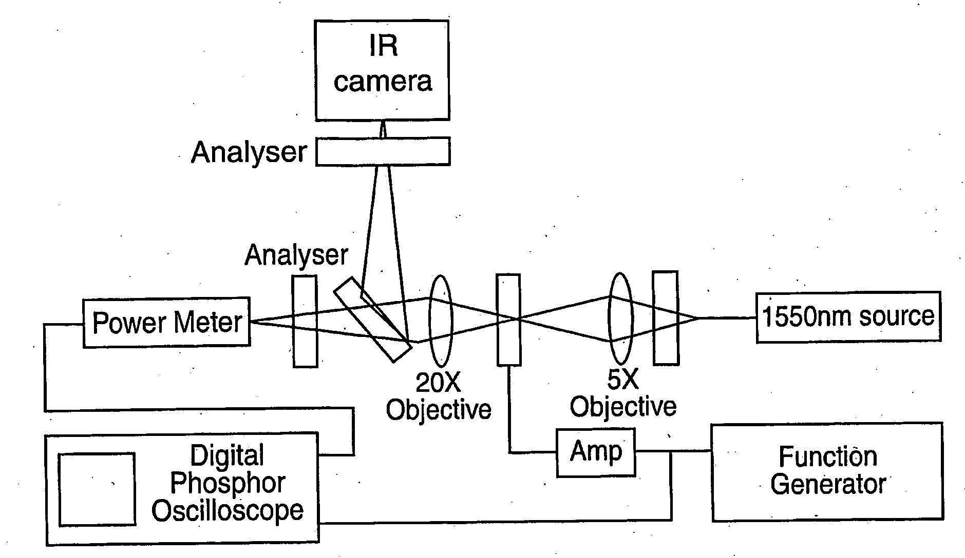
wavelength. Operating the cell at a wavelength well away from the reflection band of the chiral nematic, for example in the 1550 nm telecoms window, ensures the light will experience minimal optical activity. When a field transverse to the helical axis is applied to the
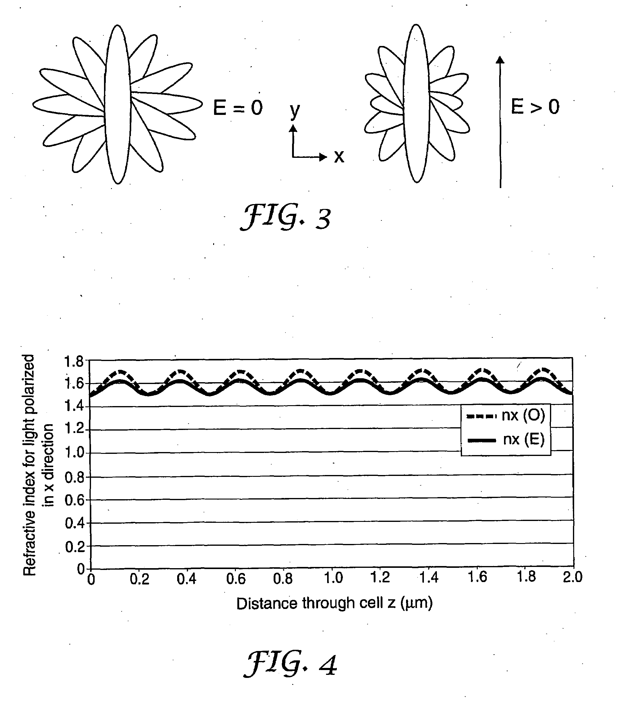
system, flexoelectric
coupling distorts the
helix such that bulk birefringence is induced which can be used to control the polarization state of incident light. An in-plane electric field deflects the optic axis from
lying along the direction of propagation to having some component in the
polarization plane of the light.
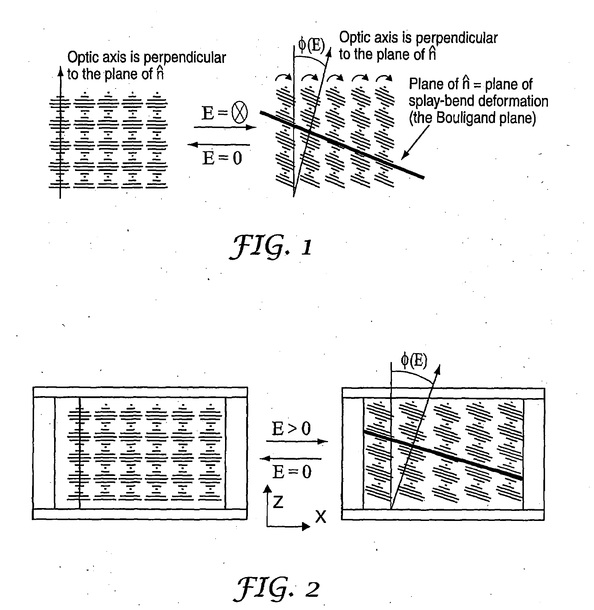
[0013]The central idea of the device proposed here however, is to rotate the geometry of the chiral nematic and the field direction within the cell, such that the application of a field now deflects the optic axis according to equation (1), but with the field in the plane of the cell, such that the optic axis moves from
lying in the direction of propagation (zero birefringence) to lying at the flexoelectric tilt angle, and therefore having some component perpendicular to the direction of propagation, inducing a birefringence. This allows the cell to be aligned in the much more reliable Grandjean (standing
helix) texture, rather than the ULH. If the cell is illuminated in the infra-red, the optical activity of a typical short pitch chiral nematic will be minimal, so the switched device will act as a straightforward fractional
waveplate. The proposed
cell geometry is illustrated in FIG. 2. It should be noted that although electrodes are shown on either side of the cell, the field in FIG. 2 is directed in the y direction into the page.

