Lens module and camera having same

a technology of lens module and lens barrel, which is applied in the direction of mounting, camera body details, instruments, etc., can solve the problems of requiring a relatively high manufacturing precision, requiring a relatively complex manufacturing process, and requiring eccentricity between the lens barrel and the holder

Inactive Publication Date: 2009-07-02
HON HAI PRECISION IND CO LTD
View PDF5 Cites 26 Cited by
  • Summary
  • Abstract
  • Description
  • Claims
  • Application Information

AI Technical Summary

Benefits of technology

[0008]A lens module includes a lens, a lens module and a base. The lens barrel receives the lens therein. The lens barrel includes a hollow cylindrical body, a beveled distal end and a flange. The hollow cylindrical body includes a smooth peripheral side surface free of thread formed thereon. The flange extends outwardly from the cylindrical body. The flange defines an annular groove in a peripheral surface thereof. The base includes a hollow cylindrical holding body coaxially receiving the cylindrical body therein. The holding body has a first distal end, a second distal end and an inner smooth surface. The beveled distal end is configured for facilitating insertion of the cylindrical body in the cylindrical holding body. The flange is configured for being clamped by a tool and being moved toward or away from the base using the tool.

Problems solved by technology

If the torque force is too strong, the rotation between the lens barrel and the holder will become difficult.
If the torque force is too weak, the lens barrel may deviate from the holder and result in eccentricity between the lens barrel and the holder.
Furthermore, regarding screw thread connection products, the structure of the screw thread teeth and the spaces between adjacent screw thread teeth may require a relatively high manufacturing precision and a relatively complex manufacturing process.
Therefore, the screw thread connection configuration used in the optical lens module may obstruct the miniaturization of the electronic product and / or may inhibit the effective mass manufacture thereof.

Method used


Image

  • Lens module and camera having same
  • Lens module and camera having same
  • Lens module and camera having same

Examples


Embodiment Construction

[0016]Reference will now be made to the drawings to describe the embodiments of the present lens module and camera, in detail.

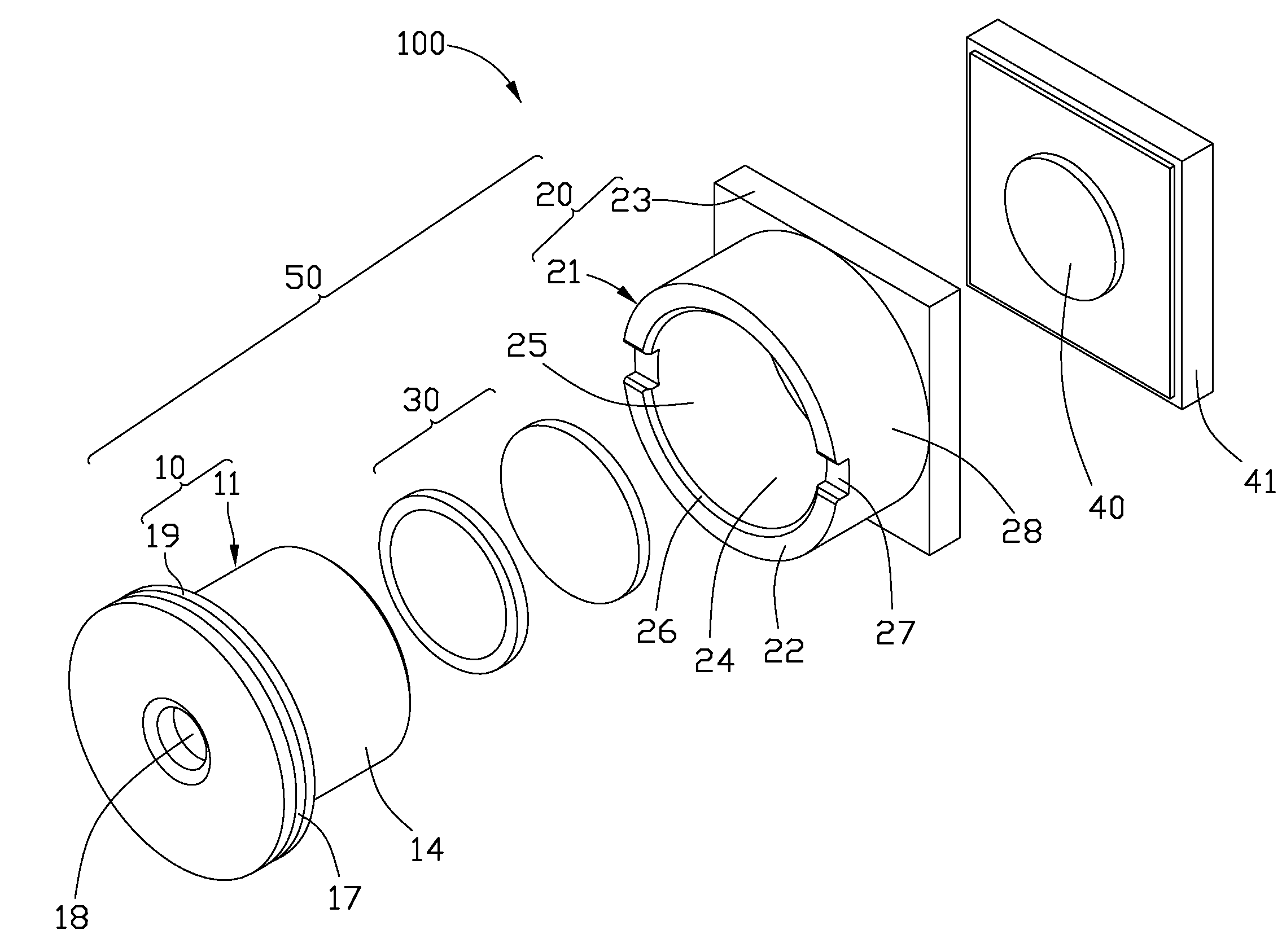
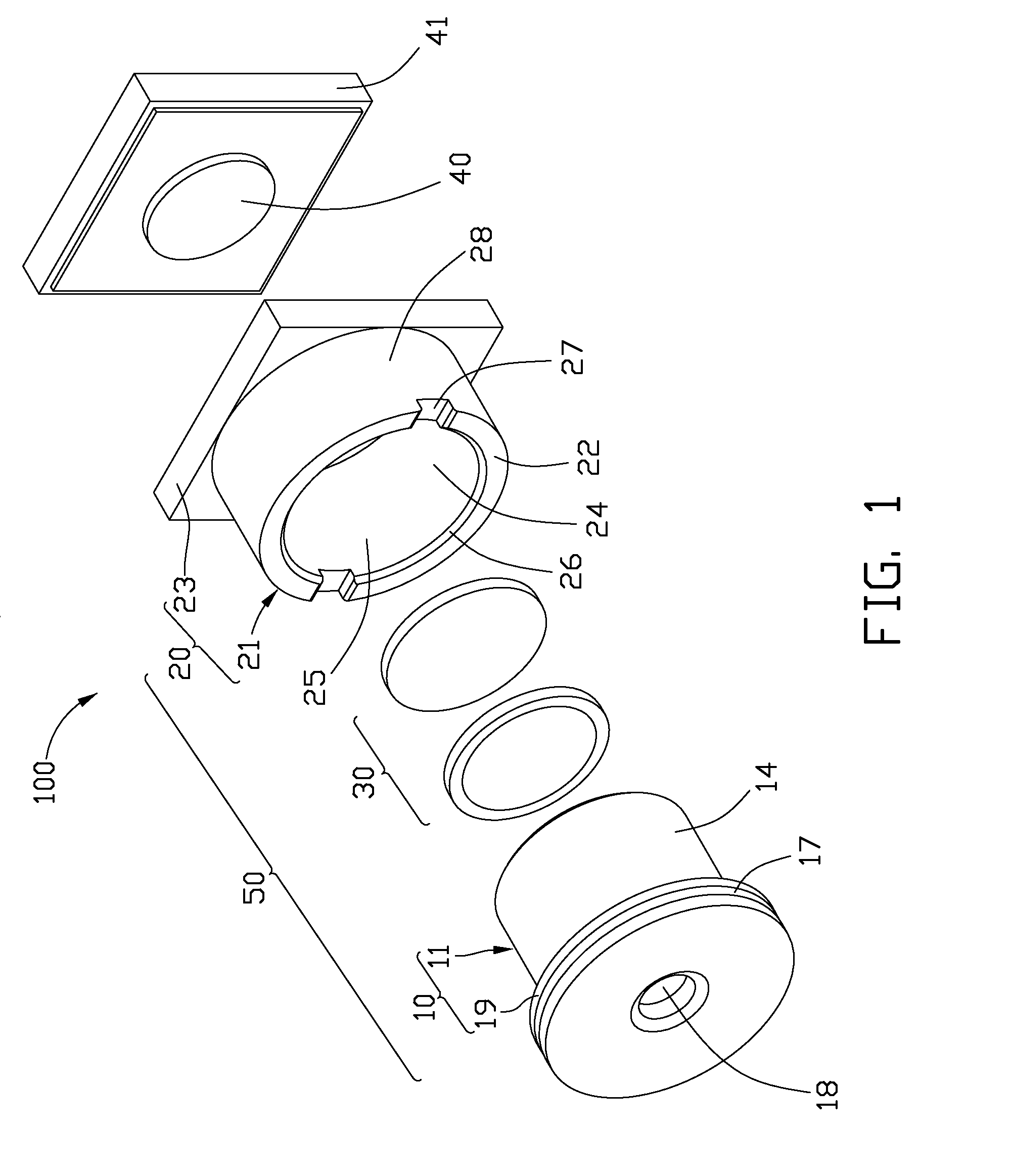
[0017]Referring to FIG. 1, a camera 100 includes a lens module 50 and an image sensor 40. The lens module 50 includes a lens barrel 10, a base 20 for receiving and holding the lens barrel 10, and a lens group 30.

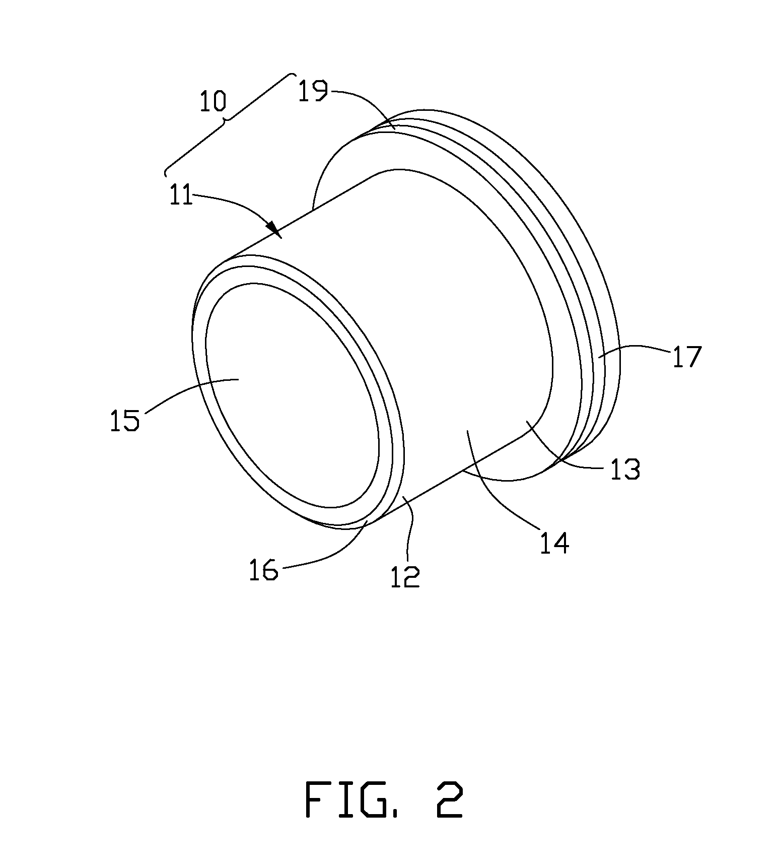
[0018]Referring to FIG. 2, the lens barrel 10 includes a hollow cylindrical body 11 having a partially-closed end 13 and an open end 12. The open end 12 is opposite to the partially-closed end 13. A peripheral side surface of the cylindrical body 11 is smooth and free of thread formed thereon. A cylindrical receiving cavity 15 is defined in the cylindrical body 11. The lens group 30 is received in the receiving cavity 15. In this embodiment, the lens group 30 includes two lenses coaxially aligned. The open end 12 includes a beveled distal end 16 having a conical shape coaxial with the hollow cylindrical body 11.

[0019]A flange 19 extends outwardly from...


PUM


Abstract

A lens module includes a lens, a lens module and a base. The lens barrel receives the lens therein. The lens barrel includes a hollow cylindrical body, a beveled distal end and a flange. The hollow cylindrical body includes a smooth peripheral side surface free of thread formed thereon. The flange extends outwardly from the cylindrical body. The flange defines an annular groove in a peripheral surface thereof. The base includes a hollow cylindrical holding body coaxially receiving the cylindrical body therein. The holding body has a first distal end, a second distal end and an inner smooth surface. The beveled distal end is configured for facilitating insertion of the cylindrical body in the cylindrical holding body. The flange is configured for being clamped by a tool and being moved toward or away from the base using the tool.

Description

BACKGROUND[0001]1. Field of the Invention[0002]The present invention relates to a lens module and a camera having the lens module.[0003]2. Description of Related Art[0004]The ongoing development in microcircuitry and multimedia technology has made digital cameras popular and in widespread use. Portable electronic devices, such as mobile phones and personal digital assistants (PDAs), are being developed to be increasingly multi-functional. Many of these portable electronic devices are now equipped with a camera module. The camera module generally includes an optical module, which includes a lens barrel and a holder for receiving the lens barrel.[0005]Generally, the lens barrel is mounted in the holder via screw threads. It is desirable to maintain a torque force between the lens barrel and the holder in an appropriate range. If the torque force is too strong, the rotation between the lens barrel and the holder will become difficult. If the torque force is too weak, the lens barrel ma...

Claims


Application Information

Patent Timeline
Patent Type & Authority Applications(United States)
IPC IPC(8): G03B17/00G02B7/02
CPCG02B7/02
Inventor CHANG, KENG-MING
Owner HON HAI PRECISION IND CO LTD
Why Eureka
Try Eureka