Tape binding device

a technology of tape binding and tape, which is applied in the direction of binding material applications, paper/cardboard containers, bundling machine details, etc., can solve the problem of partially excessive belt tension, and achieve the effect of significantly reducing the number of times of bending the belt, significantly reducing the belt tension, and partially excessive belt tension

Inactive Publication Date: 2009-07-02
TAIYO SEIKI
View PDF8 Cites 5 Cited by
  • Summary
  • Abstract
  • Description
  • Claims
  • Application Information

AI Technical Summary

Benefits of technology

[0011]In the conventional case where only one elongate belt is bent many times through a large number of pulleys, the tension of the longitudinal belt is partially excessive. On the other hand, in the present invention, the plurality of belt conveying mechanisms arranged in a polygonal shape are used. Therefore, the number of time

Problems solved by technology

In the conventional case where only one elongate belt is bent many times through a l

Method used


Image

  • Tape binding device
  • Tape binding device
  • Tape binding device

Examples


Embodiment Construction

[0040]Preferred embodiments of the present invention will be described while referring to the attached drawings.

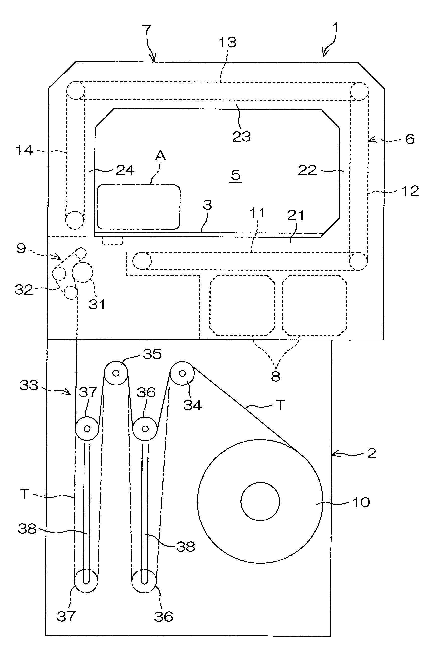
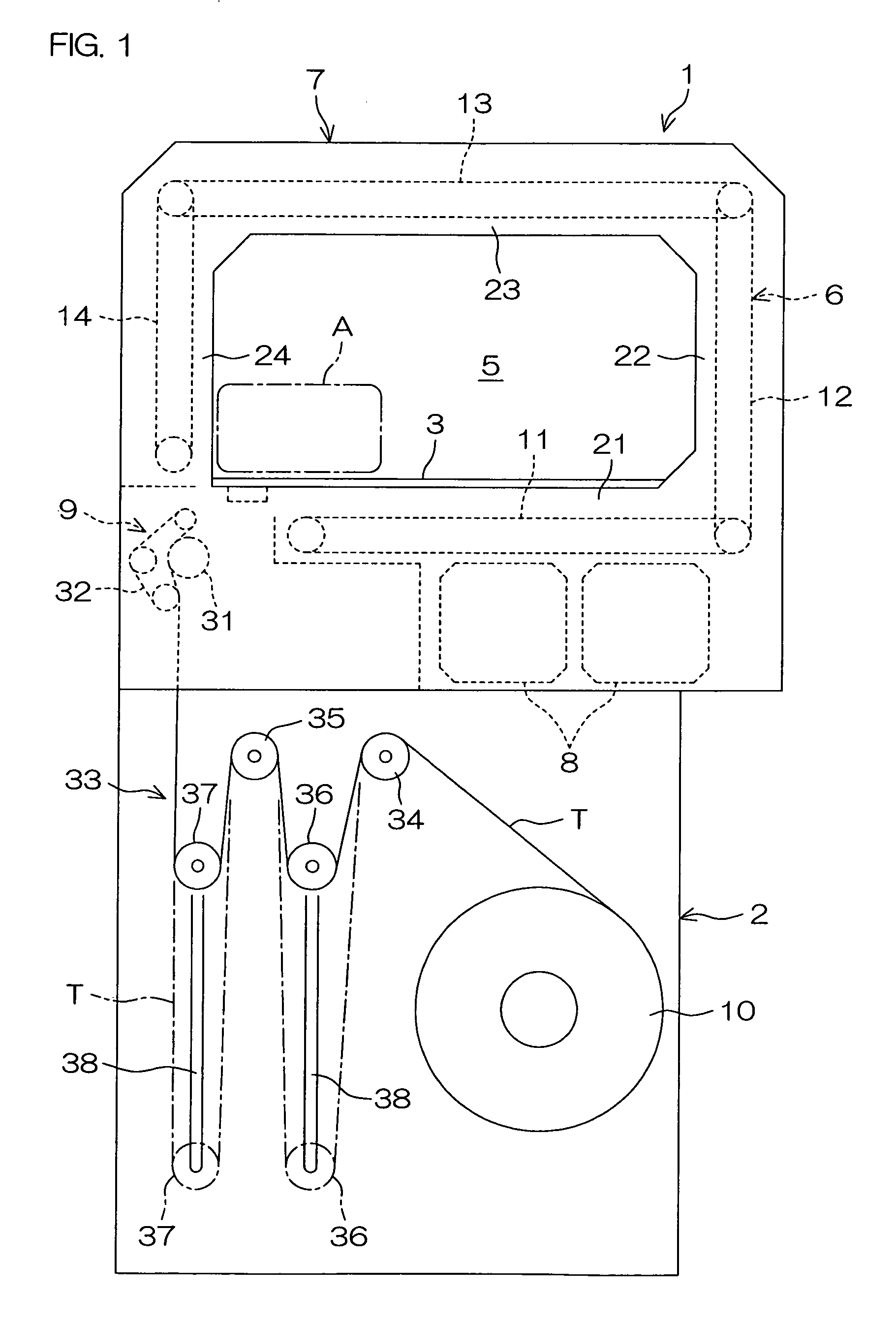
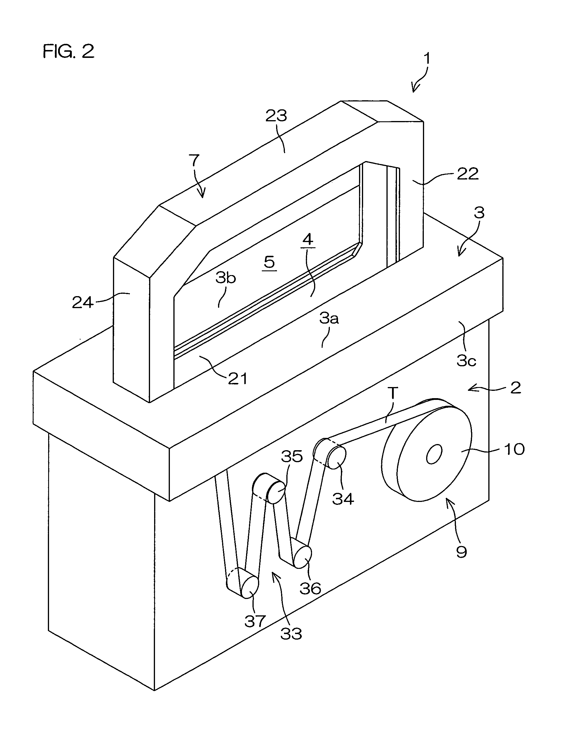
[0041]FIG. 1 is a schematic front view of a tape binding device 1 according to an embodiment of the present invention, and FIG. 2 is a schematic perspective view of the tape binding device 1. Referring to FIG. 1, the tape binding device 1 includes a device main body 2, and a table 3, on which a material to be bound A is to be placed, provided at the center in the height direction of the device main body 2. As shown in FIG. 2, a tape passage groove 4 through which a tape T for binding the material to be bound A vertically passes is formed in the table 3. The table 3 has a front part 3a and a rear part 3b sandwiching the tape passage groove 4 therebetween in the front and rear direction. Furthermore, there is provided a peripheral wall 3c extending downward from the table 3.

[0042]As shown in FIG. 1, a loop formation space 5 for forming a loop at an end of the tape T is provi...


PUM


Abstract

A tape binding device includes a loop forming mechanism for forming a loop for winding a material to be bound at an end of a tape. The loop forming mechanism includes a plurality of belt conveying mechanisms arranged in a polygonal shape in a conveyance direction for absorbing the tape by air suction and conveying the tape. Each of the belt conveying mechanisms includes a plurality of endless conveying belts extending parallel to the conveyance direction and arranged in a direction perpendicular to the conveyance direction with a space for air suction provided therebetween.

Description

BACKGROUND OF THE INVENTION[0001]1. Field of the Invention[0002]The present invention relates to a tape binding device that binds a material to be bound using a tape.[0003]2. Description of Related Arts[0004]In recent years, tape binding devices that form rectangular loops of tapes by sucking in air through a large number of holes formed in conveying belts to absorb the tapes to the conveying belts and convey the tapes are proposed (see, for example, WO95 / 019913).[0005]However, in the tape binding device disclosed in WO95 / 019913, only one belt is wound around a large number of pulleys so that the direction thereof is changed many times. Therefore, the only one belt circulates through the whole of a very long path bent at the pulleys many times. Therefore, the tension of the only one belt is liable to be partially excessive. As a result, an electric motor for driving the belt requires a very large torque. Therefore, a large-sized electric motor must be used, and thus the size of the ...

Claims


Application Information

Patent Timeline
IPC IPC(8): B65B13/04
CPCB65B13/32B65B13/04
Inventor HATAYA, HIROSHI
Owner TAIYO SEIKI
Why Eureka
Try Eureka