

Contact Member and Electrical Connector
a technology of contact member and electrical connector, which is applied in the direction of coupling base/case, coupling device connection, electrical apparatus, etc., can solve the problem of disadvantageous configuration and achieve the effect of limited width
- Summary
- Abstract
- Description
- Claims
- Application Information
AI Technical Summary
Benefits of technology
Problems solved by technology
Method used
Image

Examples
Embodiment Construction
)
[0026]An embodiment of the present invention will now be described in detail with reference to the accompanying drawings.
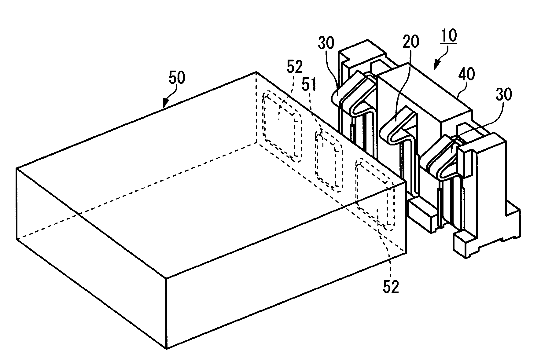
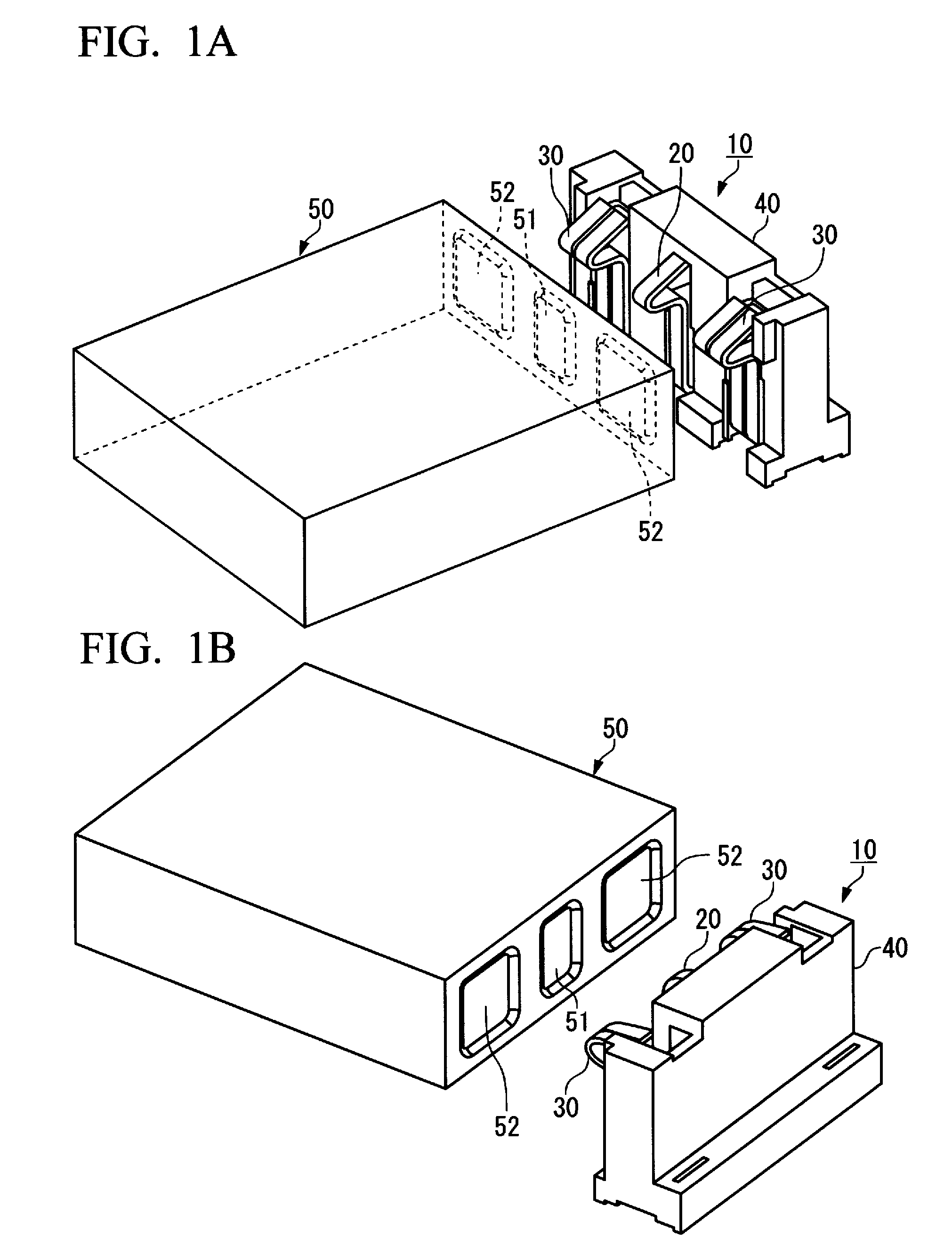
[0027]The embodiment shown in FIGS. 1A and 1B relates to a connector 10 for electrically connecting (hereinafter, referred simply to as connecting), for example, a battery cell 50 of a cellular phone handset and a printed wiring board, not shown, to each other.
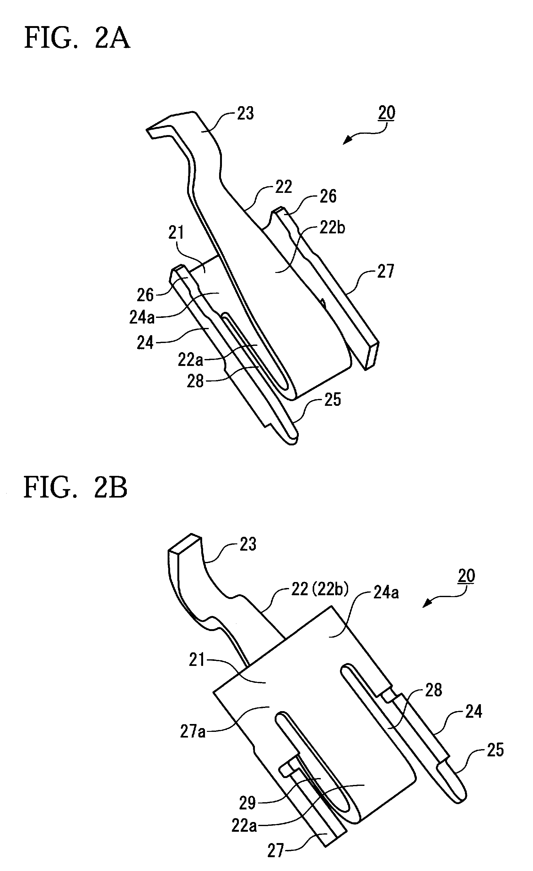
[0028]The connector 10 includes contact members 20, 30 and a housing 40 for holding the contact members 20, 30. The contact member 20 is connected to a first conductor pad 51 of the battery cell 50, and the contact member 30 is connected to the second conductor pads 52 of the battery cell 50. Each of the contact members 20, 30 are generally formed integral by stamping out a copper alloy sheet, which has high resiliency and electric conductivity. The housing 40 is generally formed integral through injection molding a resin of insulative material.
[0029]The embodiment shown features the contact members 20, 30....
PUM
 Abstract
Description
Claims
Application Information