Power split dual input shaft transmission for vehicle

a transmission and input shaft technology, applied in hybrid vehicles, fluid gearings, gearings, etc., can solve the problems of power transmission efficiency as a whole not becoming sufficiently high, power loss may be relatively increased, and power transmission efficiency may not become sufficiently high, so as to achieve easy control

Inactive Publication Date: 2009-07-02
TOYOTA JIDOSHA KK
View PDF24 Cites 29 Cited by
  • Summary
  • Abstract
  • Description
  • Claims
  • Application Information

AI Technical Summary

Benefits of technology

[0040]According to the transmission for a vehicle described above, since the shift control can be electrically performed, the control becomes easy.

Problems solved by technology

Therefore, there is possibility that as the fluid pressure becomes higher in accordance with the torque transmitted, the power loss may relatively increase, and therefore the power transmission efficiency as a whole may not become sufficiently high.
In the construction described in Japanese Patent Application Publication No. 2000-320644 (JP-A-2000-320644), since the multi-step speed change device and the HST are disposed substantially parallel to each other between the input member and the output member, there is possibility that the power transmission efficiency may not become sufficiently high due to increased power loss or the like when the power transmission via the HST is performed.
This may possibly become a factor that increases the power loss as a whole or degrades the power transmission efficiency.

Method used


Image

  • Power split dual input shaft transmission for vehicle
  • Power split dual input shaft transmission for vehicle
  • Power split dual input shaft transmission for vehicle

Examples


first embodiment

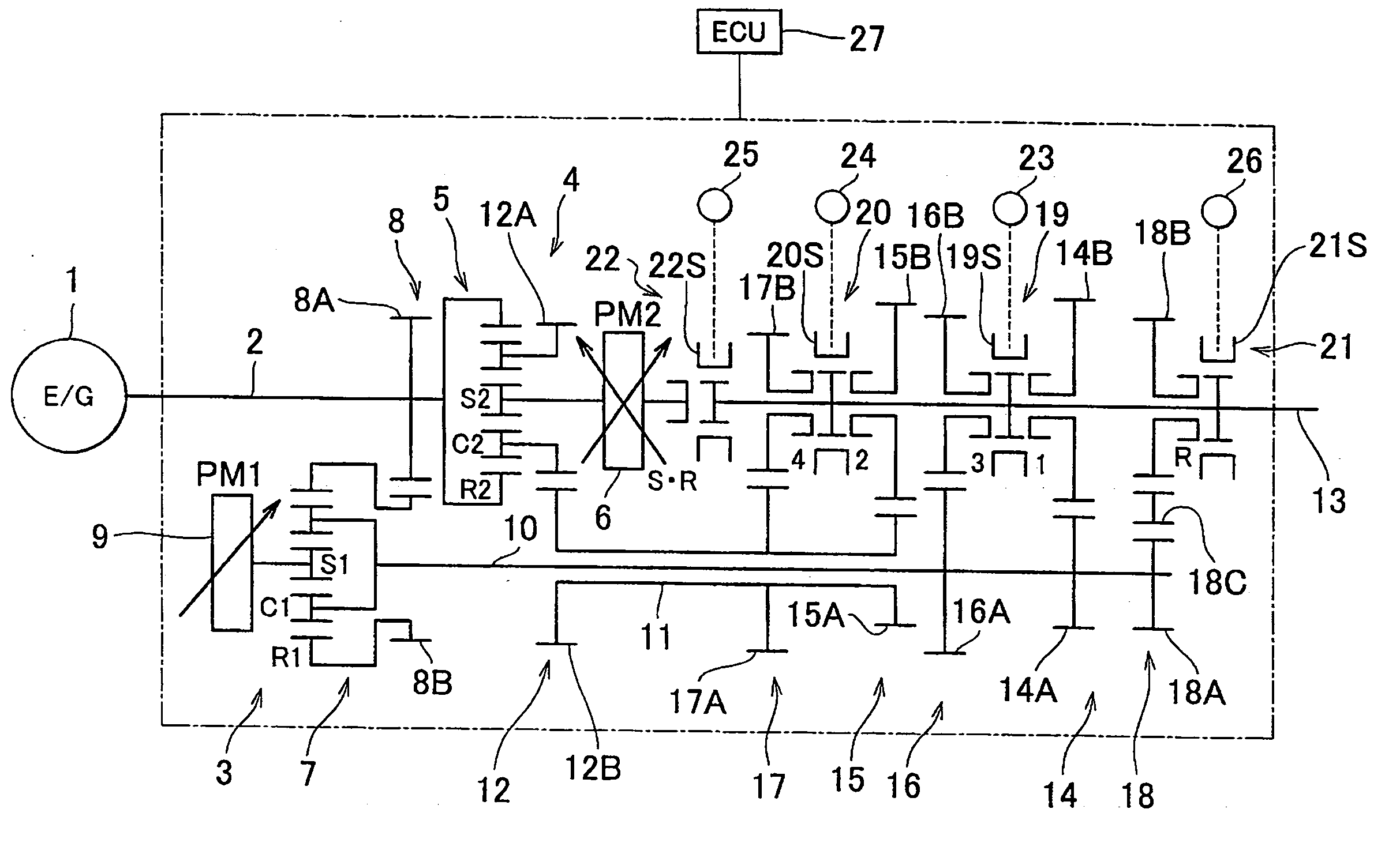
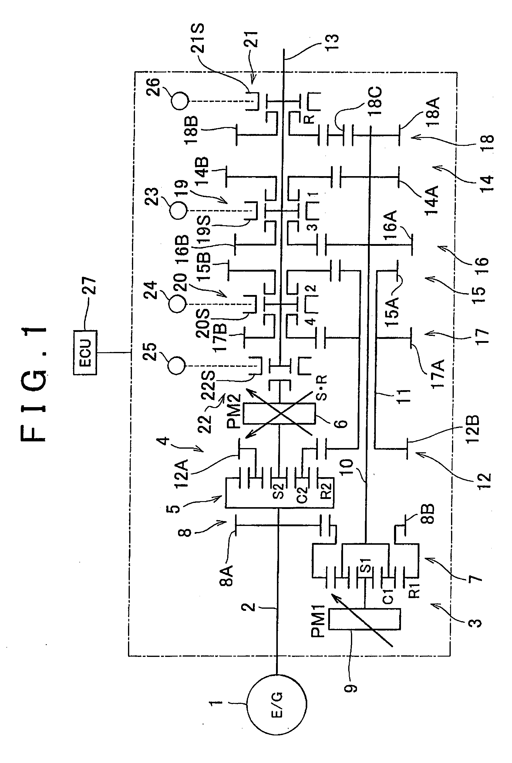
[0066]In the following description and the accompanying drawings, the present invention will be described in more detail with reference to exemplary embodiments. Firstly, a construction example of a vehicle transmission of the invention will be described with reference to FIG. 1. The example shown in FIG. 1 is a construction example in which four forward gear speeds and one reverse gear speed are set as so-called fixed speed change ratios that can be set without alteration in the form of power (energy) to be transmitted, and in particular a construction example that is adapted to an FR vehicle (a front engine, rear wheel drive vehicle) in which a motive power source 1, such as an engine or the like, is mounted in the longitudinal direction of the vehicle. Specifically, the drive units 3, 4 are disposed respectively on two axes, that is, an axis that is the same as the axis of an input member 2 linked to the motive power source 1, and an axis parallel to that axis. It is to be noted ...

second embodiment

[0112]Next, a construction example of a vehicle transmission in accordance with the invention will be described. The example shown in FIG. 4 is a construction obtained by partially alerting the construction shown in FIG. 1 so that the number of synchronizers as switching mechanisms is three and four forward gear speeds and one reverse gear speed are set. Specifically, in the construction shown in FIG. 4, the gear pairs are disposed on a driven shaft 13 and one of a first driving shaft 10 and a second driving shaft 11 in the following manner. That is, a first-speed gear pair 14, a third-speed gear pair 16 and a reverse gear pair 18 are disposed on the first driving shaft 10 in that order from the distal end side thereof (the right end side in FIG. 4), and a fourth-speed gear pair 17 and a second-speed gear pair 15 are disposed on the second driving shaft 11 in that order from the distal end side thereof. Therefore, the reverse gear pair 18 are the fourth-speed gear pair 17 are dispos...

sixth embodiment

[0152]The mechanism disposed on each of the axes is a kind of drive transmission device that directly outputs the input power, or that directly outputs a portion of the input power and converts the other power in energy form before outputting it, and that freely rotates without performing the transmission of power. In the construction example of the sixth embodiment shown in FIG. 12, the mechanism on each axis is constructed of a differential mechanism and a reaction force mechanism that applies reaction force to the differential mechanism and is able to vary the reaction force. Briefly, as for the differential mechanism, a mechanism suffices which carries out differential operation via three rotating elements. The differential mechanism may be a mechanism that has gears and rollers as rotating elements. Examples of the gear type differential mechanism that can be used as the differential mechanism herein include a single-pinion type planetary gear mechanism, and a double-pinion typ...


PUM


Abstract

A vehicle transmission includes at least two driving shafts to which power is transmitted from a power source, a driven shaft to which power is transmitted from the driving shafts, drive transmission mechanisms disposed between the driving shafts and the driven shaft, and a switching mechanism that selectively enables power transmission via the drive transmission mechanisms. The driving shafts are disposed concentrically and fitted rotatably relative to each other. The driving shafts are parallel to the driven shaft. A first drive unit is disposed coaxially with the driving shafts. A second drive unit is disposed coaxially with the driven shaft. The first and second drive units are interconnected so as to send and receive powers changed in energy form to and from each other. The transmission thus constructed is excellent in power transmission efficiency, quietness, vehicle mountability, etc., and can realize continuously variable speed change.

Description

BACKGROUND OF THE INVENTION[0001]1. Field of the Invention[0002]The invention relates to a transmission for a vehicle which includes a plurality of drive transmission mechanisms, such as gear pairs and the like, in power transmission lines and which performs the shifting of the transmission speed ratio by changing the drive transmission mechanisms involved in the torque transmission. In particular, the invention relates to a transmission capable of using a combination of the power transmission by mechanical means, such as gear mechanisms or the like, and the power transmission via hydraulic pressure of pressure fluid or the like, or another form of energy, such as electric power or the like.[0003]2. Description of the Related Art[0004]An example of the foregoing type of transmission is described in Japanese Patent Application Publication No. 11-51150 (JP-A-11-51150). A transmission described in Japanese Patent Application Publication No. 11-51150 (JP-A-11-51150) is constructed of a ...

Claims


Application Information

Patent Timeline
Patent Type & Authority Applications(United States)
IPC IPC(8): F16H3/72B60K6/36B60K6/365F16H37/08B60K6/445B60W10/10B60W10/11F16H47/04
CPCB60K6/36Y10T477/23B60K6/445B60W10/103B60W10/113F16H3/006F16H3/728F16H47/04F16H2037/0873F16H2037/102F16H2037/108F16H2200/0043F16H2200/2007Y02T10/6239B60K6/365Y02T10/62
Inventor MURAKAMI, AKIRAFUNAHASHI, MAKOTOSHIINA, TAKAHIRO
Owner TOYOTA JIDOSHA KK
Why Eureka
Try Eureka