
Bending instrument for an endoscope and endoscope set

a technology of endoscope and endoscope set, which is applied in the field of bending instruments, can solve the problems of soiled, discomfort for patients, and exposed portion of ultrasonic probes

Active Publication Date: 2009-07-02
KPR U S LLC
View PDF11 Cites 8 Cited by
  • Summary
  • Abstract
  • Description
  • Claims
  • Application Information

AI Technical Summary

Benefits of technology

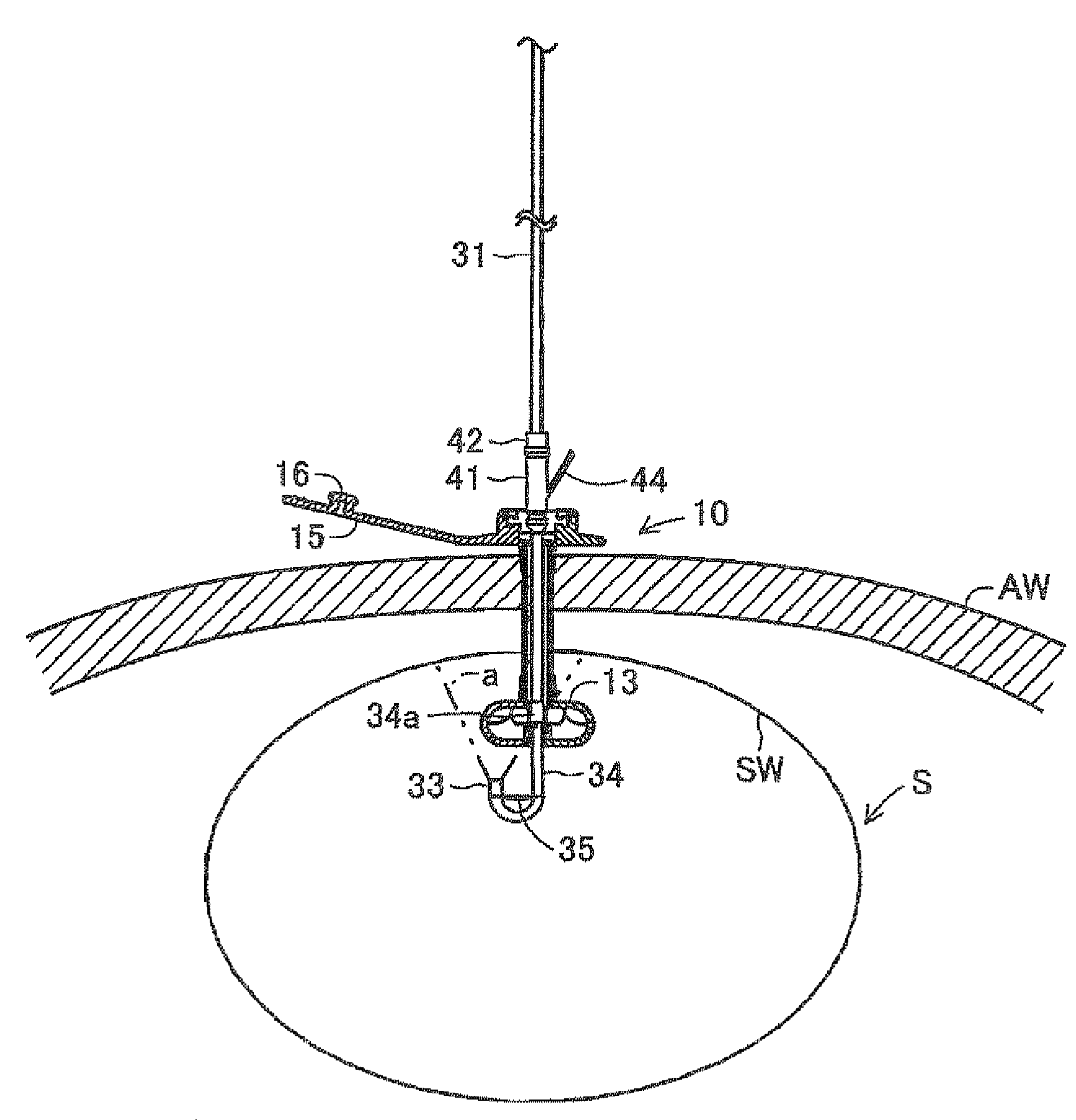
[0007]In one aspect, the invention is directed to a bending instrument for an endoscope a tubular part formed with an internal through-hole, and an intra-stomach fixed part which is joined to the tip end of the tubular part in a state in which the tip end of the through-hole of the tubular part is open and which is provided with an engagement part in the vicinity of the tip end of the through-hole. The bending instrument is used when an endoscope is inserted into an indwelling gastrostomy catheter such that the tubular part is positioned in a gastrostomy hole formed between the surface of a patient's skin and the inner surface of the stomach wall and also such that the intra-stomach fixed part is positioned inside the stomach. The bending instrument for an endoscope comprises: a sheath; a bending member; a sliding part; and a linking part. The sheath can pass inside the gastrostomy catheter together with the endoscope in a manner such that it covers the endoscope, and it has a light-transmissive window part formed at its tip end. The bending member comprises a fixed part which is attached to the tip end outer periphery of the sheath in a manner such that it cannot move to the base end side of the sheath and such that it can pass inside the gastrostomy catheter together with the sheath. The sliding part is slidably attached further to the base end side of the sheath than the site of attachment of the fixed part, and can pass through the through-hole of the gastrostomy catheter, but engages with the engagement part of the intra-stomach fixed part so as not to be able to go past the intra-stomach fixed part. The linking part links the fixed part and the sliding part, thereby controlling the gap between the fixed part and the sliding part so that it does not exceed a specified length.

Problems solved by technology

The stomach wall or the like of a patient is conventionally observed by inserting an endoscope nasally or orally into the stomach, or the like, but this method can cause discomfort to the patient.
Consequently, the exposed portion of the ultrasonic probe comes into direct contact with bodily fluids etc. from various parts of the body during use, and becomes soiled.
Furthermore, with the bending sheath for a probe described above, the cap comprises a member that is closed at its tip end, and therefore it cannot be used with an endoscope for capturing images by focusing using a lens.

Method used


Image

  • Bending instrument for an endoscope and endoscope set
  • Bending instrument for an endoscope and endoscope set
  • Bending instrument for an endoscope and endoscope set

Examples


embodiment 1 first embodiment

Mode of Embodiment 1 First Embodiment

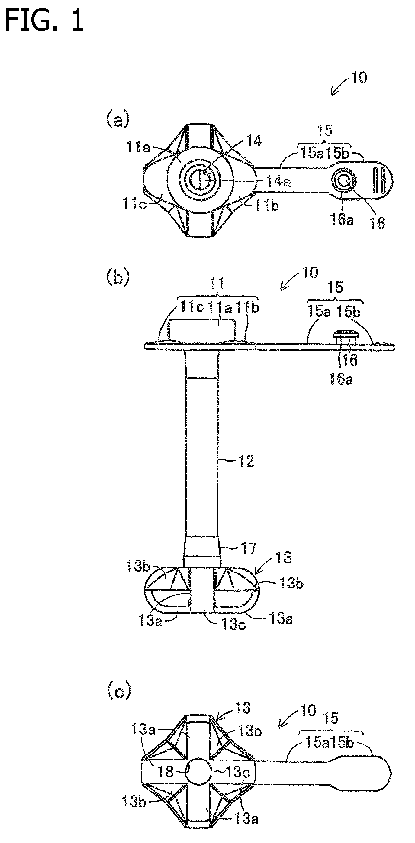
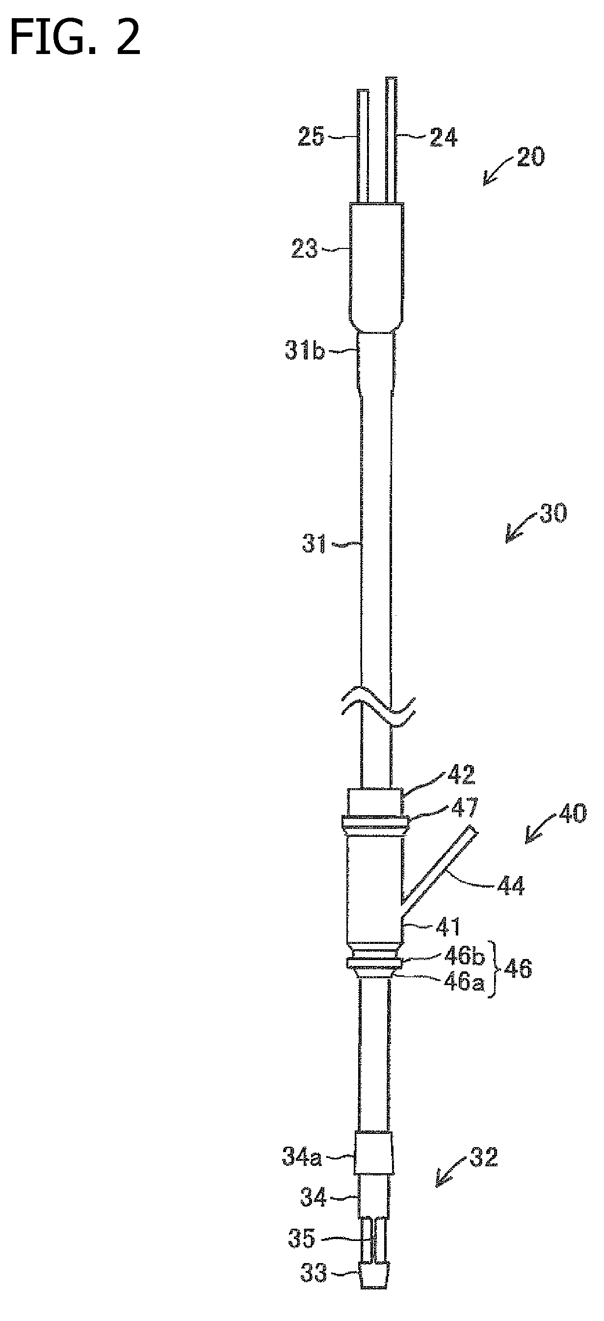
[0043]The first embodiment of the present invention will be described below with reference to the figures. FIG. 1 shows a gastrostomy catheter 10 which is used in this embodiment, and FIG. 2 shows a state in which a bending instrument 30 for an endoscope is fitted to a fibrescope 20 which acts as the endoscope according to the present invention which passes inside the gastrostomy catheter 10. The endoscope set according to the present invention comprises the gastrostomy catheter 10, fibrescope 20 and bending instrument 30 for an endoscope. The gastrostomy catheter 10 comprises an external fixed part 11, a tubular part 12 which is linked to the center of the lower end surface of the external fixed part 11, and an intra-stomach fixed part 13 which is attached to the lower end of the tubular part 12, all these components being made of a soft plastic material such as polyurethane or silicone. In the description that follows, the external fixed part 1...

embodiment 2 second embodiment

Mode of Embodiment 2 Second Embodiment

[0081]FIG. 14 shows a sheath 51 for a bending instrument for an endoscope according to the second embodiment of the present invention. With this sheath 51, an accordion-like part 52 comprising a plurality of protrusions which configure the protrusions of the present invention is formed at the lower end portion lying between the fixed part 33 and the sliding part 34 when the abovementioned bending member 32 is fitted. The configuration of the other components of the bending instrument for an endoscope provided with this sheath 51 is the same as that of the bending member 32 described above.

[0082]Accordingly, similar components bear similar reference numbers and a description of them will be omitted. This allows the accordion-like part 52 portion of the sheath 51 to bend easily, and makes it possible to prevent folds occurring in the sheath 51. Furthermore, said accordion-like part 52 also acts as the retaining protrusions for preventing the slidi...

embodiment 3

Mode of Embodiment 3 The Third Embodiment

[0083]FIG. 15 shows a bending member 62 for a bending instrument for an endoscope according to a third embodiment of the present invention. With this bending member 62, a resistance-imparting projection 67 which is elongate and shaped like a thin board is formed at the tip end portion of a sliding part 66, i.e. the upper part of the narrow diameter portion which constitutes the tip end portion according to the present invention. This resistance-imparting projection 67 extends obliquely towards the base end side of the sliding part 66 from a portion on the opposite side to the portion provided with a linear linking part 65 on the outer peripheral surface of the sliding part 66.

[0084]The resistance imparting projection 67 is then pressured at the tip end of the sliding part 66, whereby it simply bends so as to lie along the outer peripheral surface of the sliding part 66, and by applying a fairly large force towards the base end of the sliding ...


PUM


Abstract

A bending instrument for an endoscope which is used when a fibrescope is inserted into a gastrostomy catheter. The bending instrument comprises a sheath which covers a fibrescope shaft of the fiberscope, and a bending member which allows the fibrescope shaft to bend together with the sheath. A light-transmissive window part is formed at the tip end of the sheath. Furthermore, the bending member comprises a fixed part which is attached to the tip end outer periphery of the sheath, a sliding part which is slidably attached further to the base end side of the sheath than the fixed part and which engages with a cylindrical engagement part of the gastrostomy catheter so as not to be able to go past an intra-stomach fixed part, and a linear linking part which links the fixed part and the sliding part.

Description

FIELD OF THE INVENTION[0001]The present invention relates to a bending instrument for an endoscope which is used when a gastrostomy catheter is indwelling in a gastrostomy hole formed in a patient's body, and an endoscope is inserted into said gastrostomy catheter to observe the interior of the stomach, and to an endoscope set provided therewith.BACKGROUND OF THE INVENTION[0002]The stomach wall or the like of a patient is conventionally observed by inserting an endoscope nasally or orally into the stomach, or the like, but this method can cause discomfort to the patient. Consequently, it has become necessary in recent practice to make a gastrostomy catheter indwelling in a gastrostomy hole formed in the patient's body and to observe the interior of the stomach by passing an endoscope inside said gastrostomy catheter so as to confirm the indwelling position of the gastrostomy catheter. In such cases it is necessary to be able to change the orientation of the tip end of the endoscope ...

Claims


Application Information

Patent Timeline
Patent Type & Authority Applications(United States)
IPC IPC(8): A61B1/008A61B1/00
CPCA61B1/01A61B1/00135
Inventor SUTOH, DAI
Owner KPR U S LLC
Learn More