Endoscope and attaching method of connection mouth ring to end of endoscopic flexible tube

Active Publication Date: 2009-07-02
OLYMPUS CORP
View PDF11 Cites 23 Cited by
  • Summary
  • Abstract
  • Description
  • Claims
  • Application Information

AI Technical Summary

Benefits of technology

[0008]According to a first aspect of the invention, there is provided an endoscope including a flexible tube, a connection mouth ring, and a helical tube displacement preventing portion. The flexible tube includes a helical tube in which a thin strip plate is helically wound, a braid tube covering the outside of the helical tube, and a flexible outer tube covering the out

Problems solved by technology

However, braze welding requires a subsequent flux cleaning proces

Method used


Image

  • Endoscope and attaching method of connection mouth ring to end of endoscopic flexible tube
  • Endoscope and attaching method of connection mouth ring to end of endoscopic flexible tube
  • Endoscope and attaching method of connection mouth ring to end of endoscopic flexible tube

Examples


Example

[0031]A first embodiment is described with reference to FIG. 1 to FIG. 6F.

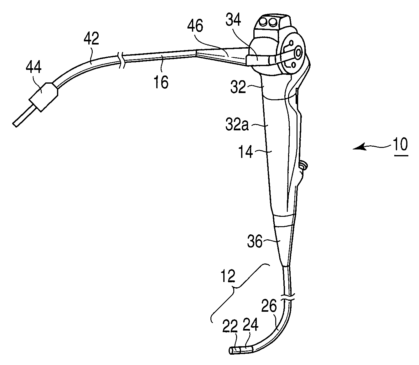
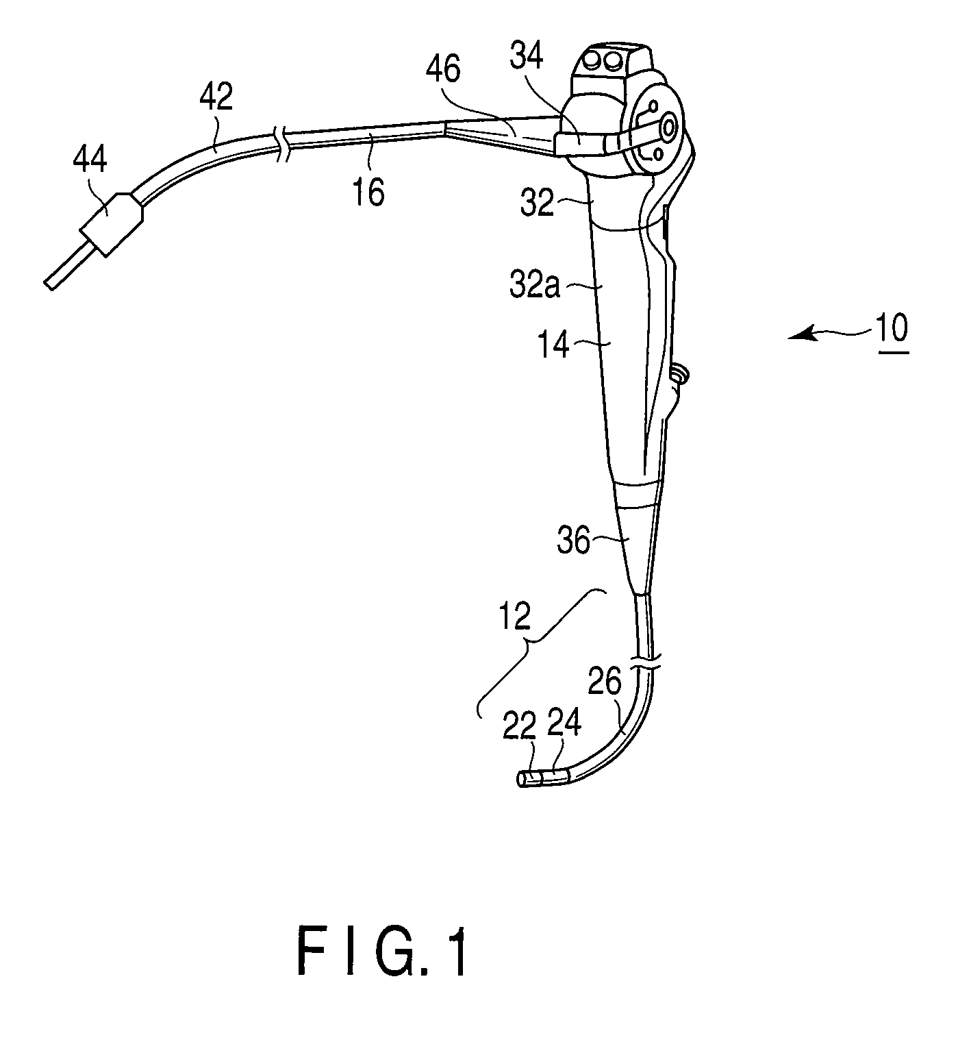
[0032]As shown in FIG. 1, an endoscope 10 includes an insertion portion 12 to be inserted into a narrow and small space, an operation portion 14 disposed at the proximal end of the insertion portion 12, and a universal cable 16 extending from the operation portion 14.

[0033]The insertion portion 12 includes a distal hard portion 22, a bending portion 24 disposed at the proximal end of the distal hard portion 22, and a flexible tube (corrugated tube) 26 disposed at the proximal end of the bending portion 24. The operation portion 14 includes an operation portion main body 32 with a grip portion 32a, a bending operation knob 34 disposed in the operation portion main body 32, and an protection hood 36 disposed at the proximal end of the flexible tube 26 and disposed in the grip portion 32a of the operation portion main body 32. The universal cable 16 includes a flexible tube 42 extending from the operation portion...

Example

Second Embodiment

[0072]Next, a second embodiment is described with reference to FIG. 7. This embodiment is a modification of the first embodiment, and the same symbols are assigned to the same members as the members described in the first embodiment or the members having the same effects, and such members are not described in detail. This holds true with the third to twelfth embodiments.

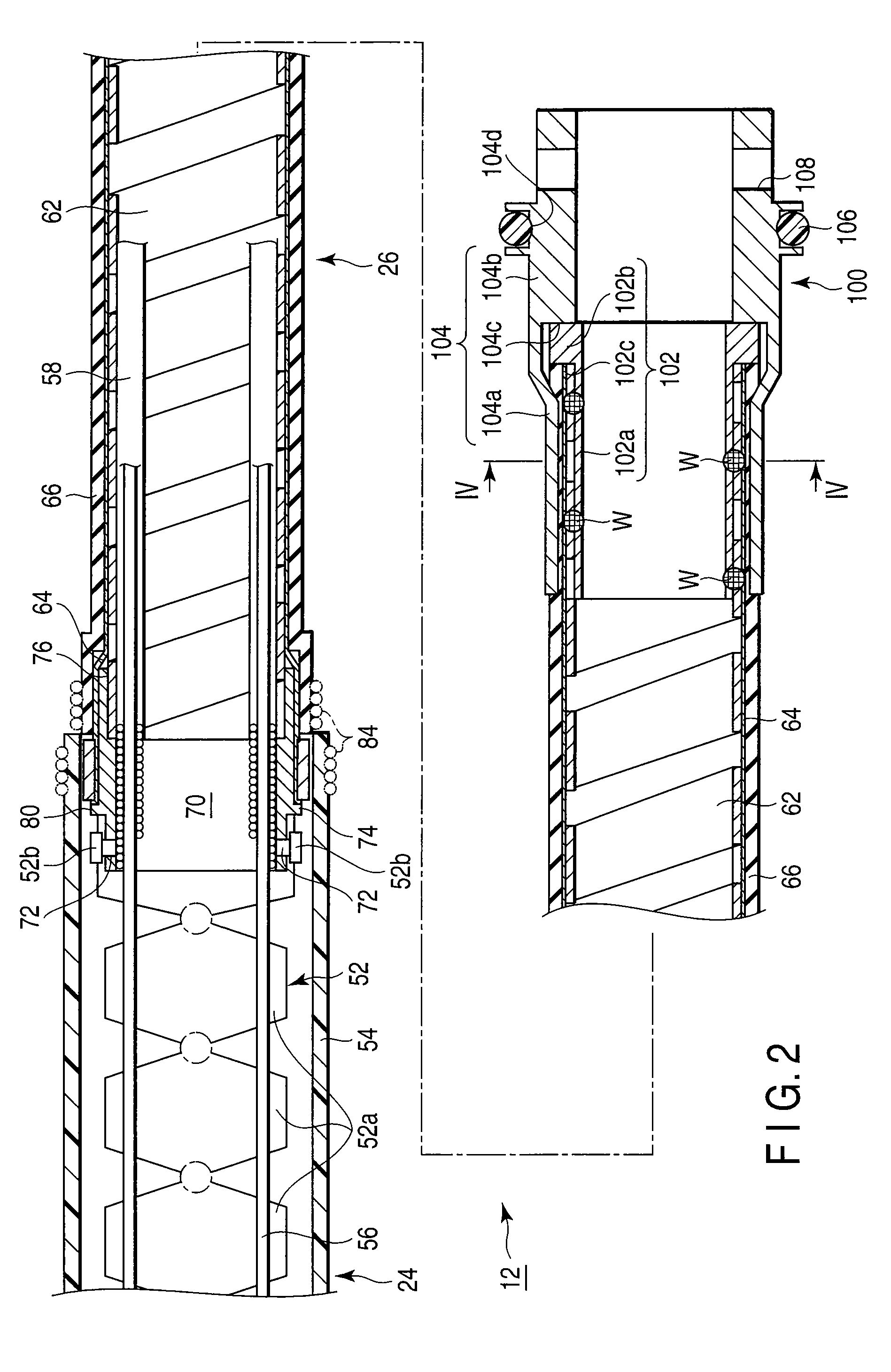
[0073]In the example of this embodiment, the structure used to fix the second connection mouth ring 100 to the proximal end of the flexible tube 26 shown in FIG. 2 in the first embodiment is used to fix a first connection mouth ring 70 to the distal end of the flexible tube 26, as shown in FIG. 7. That is, the structure for fixing the first connection mouth ring 70 to the distal end of the flexible tube 26 in this embodiment is the same as the structure for fixing the second connection mouth ring 100 to the proximal end of the flexible tube 26 described in the first embodiment.

[0074]The first connect...

Example

Third Embodiment

[0087]Next, a third embodiment is described with reference to FIG. 8.

[0088]As shown in FIG. 8, a convex-concave portion 142 having a convex portion (crest portions) 142a and a concave portion (root portions) 142b is formed in the inner peripheral surface of the cylindrical portion 104a of the outer mouth ring 104 of the second connection mouth ring 100 in this embodiment. When the cylindrical portion 104a of the outer mouth ring 104 is caulked inward, the convex portion 142a in the inner peripheral surface of the cylindrical portion 104a of the outer mouth ring 104 cuts into the outer tube 66, so that greater fixing strength can be obtained when the second connection mouth ring 100 is fixed to the proximal end of the flexible tube 26.

[0089]Further, the convex-concave portion 142 may be formed as a female screw thread, for example. Moreover, if the convex portion 142a is formed on the inside of the cylindrical portion 104a of the outer mouth ring 104, various shape ar...


PUM


Abstract

An endoscope includes a flexible tube having a helical tube in which a thin strip plate is helically wound, a braid tube covering the outside of the helical tube, and a flexible outer tube covering the outside of the braid tube, a connection mouth ring plastically deformed and fixed to an end of the flexible tube, and a helical tube displacement preventing portion which prevents displacement of the strip plate of the helical tube at the end of the flexible tube to which the connection mouth ring is fixed, when the connection mouth ring is fixed to the end of the flexible tube.

Description

CROSS-REFERENCE TO RELATED APPLICATIONS[0001]This application is based upon and claims the benefit of priority from prior Japanese Patent Application No. 2007-335326, filed Dec. 26, 2007, the entire contents of which are incorporated herein by reference.BACKGROUND OF THE INVENTION[0002]1. Field of the Invention[0003]This invention relates to an endoscope which can be used for various purposes such as medical and industrial purposes, and an attaching method of connection mouth ring to an end of an endoscopic flexible tube.[0004]2. Description of the Related Art[0005]Heretofore, in manufacturing a flexible tube (flexible tube) used for an insertion portion or a universal cable of an endoscope, generally, a connection mouth ring has been fixed by adhesive bonding to a portion (hard portion) where a helical tube and a braid tube are braze-welded. However, braze welding requires a subsequent flux cleaning process, and the adhesive bonding requires time to complete the drying.[0006]Thus, ...

Claims


Application Information

Patent Timeline
IPC IPC(8): A61B1/00
CPCA61B1/0011G02B23/2476A61B5/0002A61B1/005
Inventor MATSUO, SHIGEKIUMETA, TAKATOSHIKOSUKI, SHIGERU
Owner OLYMPUS CORP
Why Eureka
Try Eureka