Control device for automatic transmission

a control device and automatic transmission technology, applied in mechanical equipment, instruments, gearing, etc., can solve the problems of reducing the size of the hydraulic control device, inhibiting the reduction in weight and cost, and increasing the number of necessary cut-off valves, so as to reduce the size, weight and cost

Active Publication Date: 2009-07-02
AISIN AW CO LTD
View PDF11 Cites 34 Cited by
  • Summary
  • Abstract
  • Description
  • Claims
  • Application Information

AI Technical Summary

Benefits of technology

This patent describes a new way to control an automatic transmission that prevents two parts from being engaged at once (called simultaneous engagement) without adding extra components or increasing costs. It achieves this by making use of existing technology and has several benefits over traditional methods.

Problems solved by technology

The technical problem addressed by this patent is how to prevent multiple friction engagement elements from being engaged at the same time in an automatic transmission system caused by failures such as disconnection or valve stickiness.

Method used


Image

  • Control device for automatic transmission
  • Control device for automatic transmission
  • Control device for automatic transmission

Examples


Embodiment Construction

[0019]Hereinafter, an embodiment of the present invention will be described with reference to FIGS. 1 to 8B.

[Schematic Configuration of Automatic Transmission]

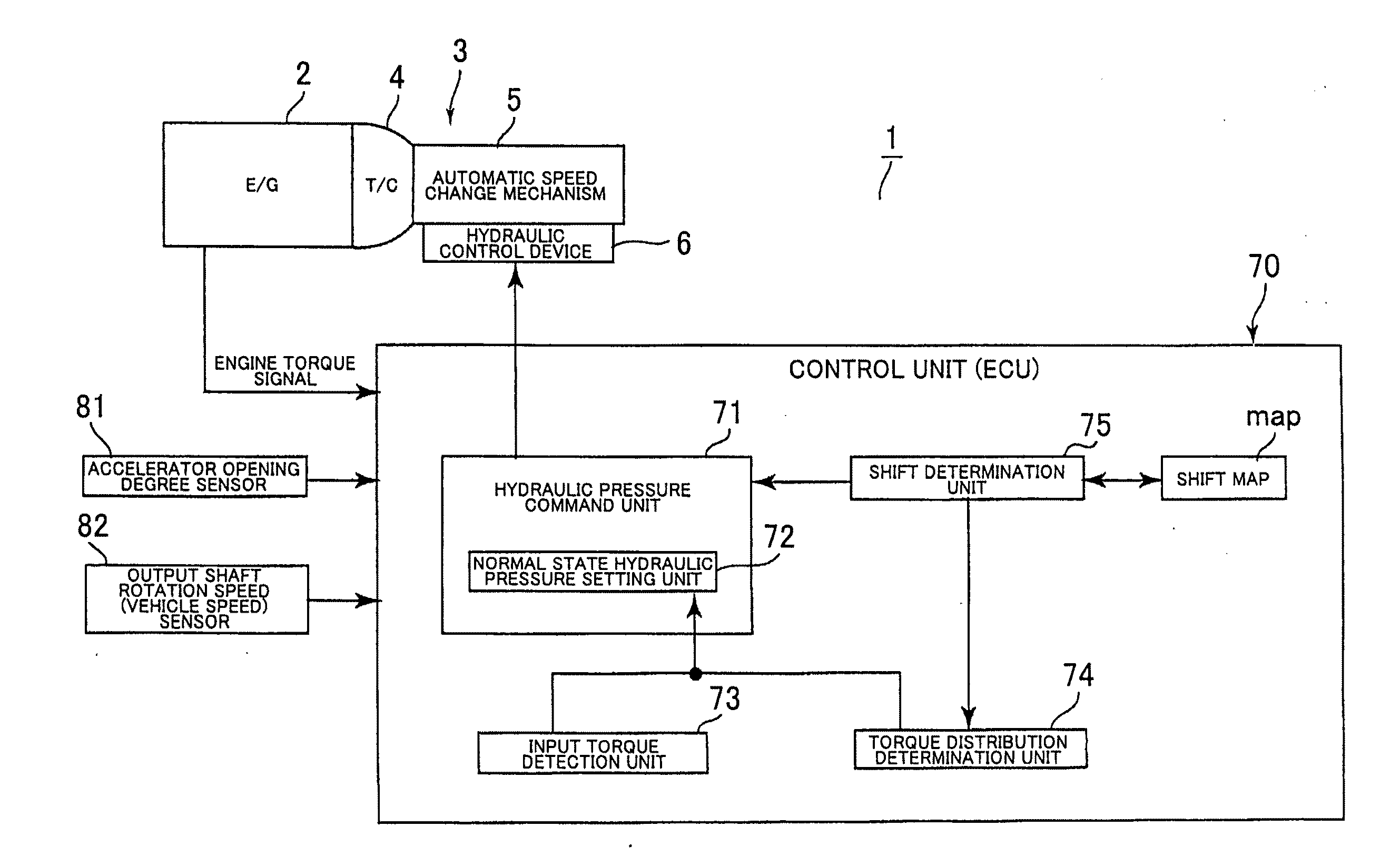
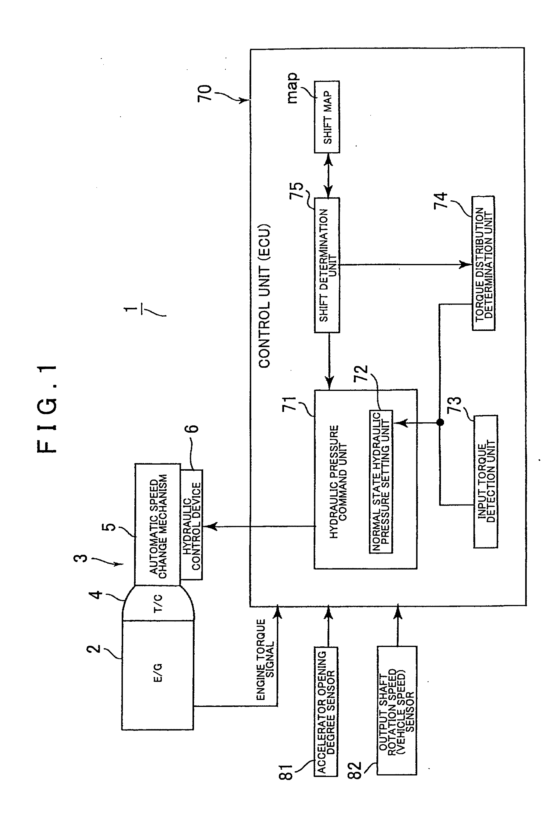
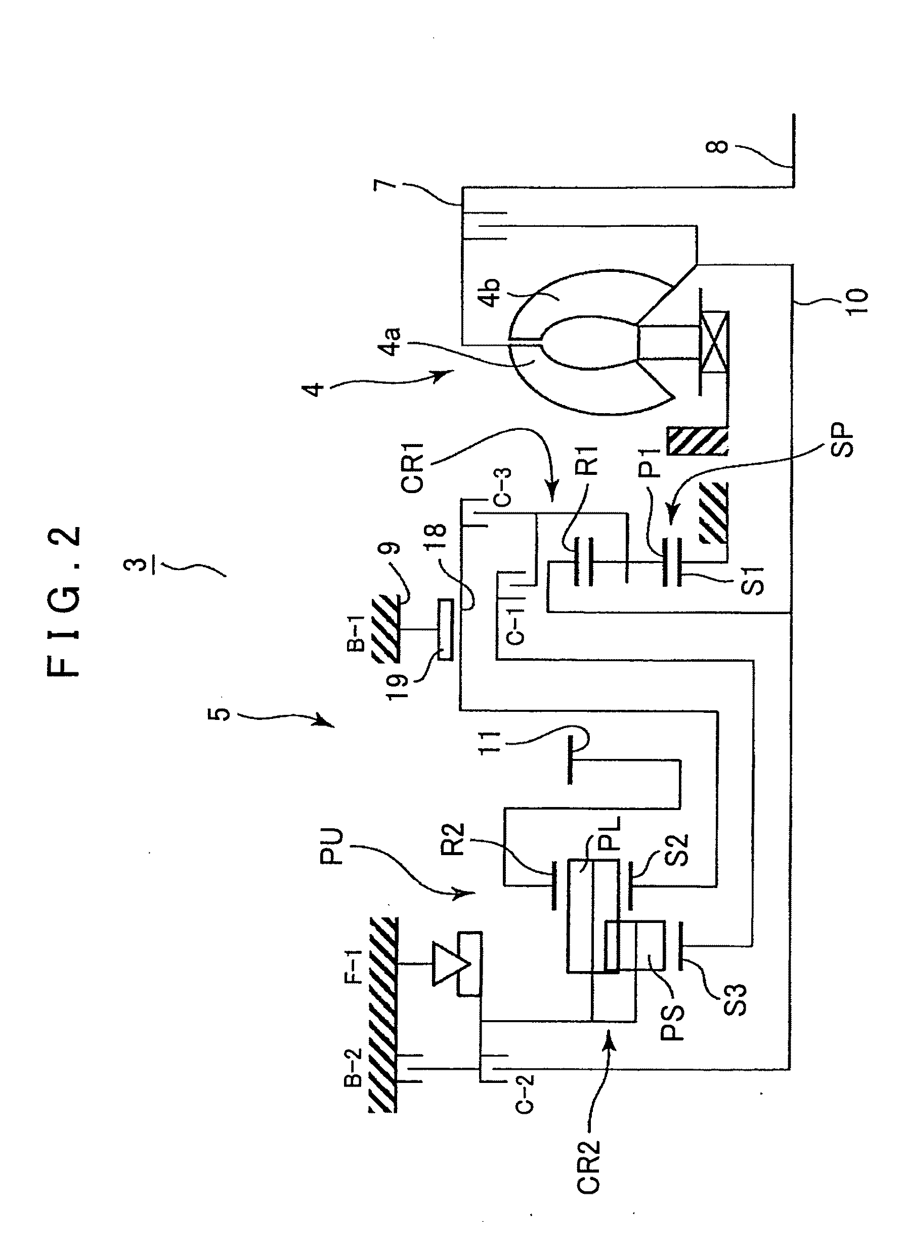
[0020]First, the schematic configuration of an automatic transmission 3 to which the present invention can be applied will be described with reference to FIG. 2. For example, as shown in FIG. 2, the automatic transmission 3 suitable for use in a front-engine front-wheel drive (FF) vehicle has an input shaft 8 of the automatic transmission connectable to an engine (driving source) 2 (see FIG. 1), and includes a torque converter 4 and an automatic speed change mechanism 5 with the axis of the input shaft 8 as the center.

[0021]The torque converter 4 has a pump impeller 4a connected to the input shaft 8 of the automatic transmission 3, and a turbine runner 4b to which the rotation of the pump impeller 4a is transmitted via a working fluid. The turbine runner 4b is connected to an input shaft 10 of the automatic speed change mechan...


PUM


Abstract

An exemplary control device includes an input torque detection unit that detects an input torque input to the input shaft; and a controller that: determines torque distribution of two of the friction engagement elements that form the shift speeds; and calculates a transmission torque of the two friction engagement elements based on the input torque and the torque distribution and sets the engagement pressure to obtain a torque capacity that can transmit the transmission torque, wherein the controller sets the engagement pressure such that slippage does not occur in the two friction engagement elements in a state where engagement of the two friction engagement elements forms the shift speeds and such that, even if an additional friction engagement element engages based on the line pressure while the two friction engagement elements are engaged, one of the three friction engagement elements is caused to slip.

Description


Claims


Application Information

Patent Timeline
Owner AISIN AW CO LTD
Why Eureka
Try Eureka