Condenser

a technology of condensers and condensers, which is applied in the field of condensers, can solve the problems of reducing the refrigeration efficiency of the refrigeration cycle and affecting the condensation performance, and achieve the effect of effectively suppressing reducing the impairment of condensation performan

Inactive Publication Date: 2009-07-09
SHOWA DENKO KK
View PDF4 Cites 18 Cited by
  • Summary
  • Abstract
  • Description
  • Claims
  • Application Information

AI Technical Summary

Benefits of technology

[0029]The condenser according to par. 1) produces a remarkable effect when the total number of refrigerant tubes is 22 to 70 as described in par. 3).
[0030]The condenser according to par. 1) produces a remarkable effect when the refrigerant contains 3 to 10 mass % of compressor lubricant as described in par. 5).
[0031]With the condenser described in par. 6), the upper-end tube group has up to 21 refrigerant tubes below the center of the refrigerant inlet with respect to the vertical direction, so that even when containing the compressor lubricant, refrigerant readily flows into the refrigerant tubes positioned in the lower portion of the up

Problems solved by technology

The presence of the compressor lubricant in the refrigerant entails the problem of impairing

Method used


Image

  • Condenser
  • Condenser
  • Condenser

Examples


example 1

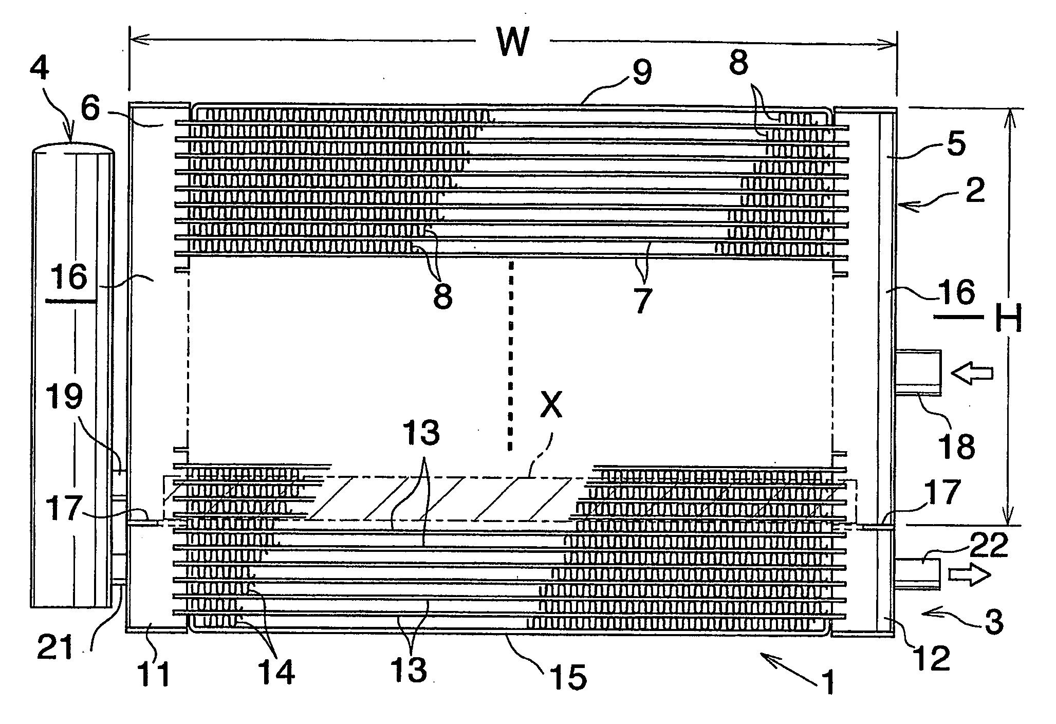
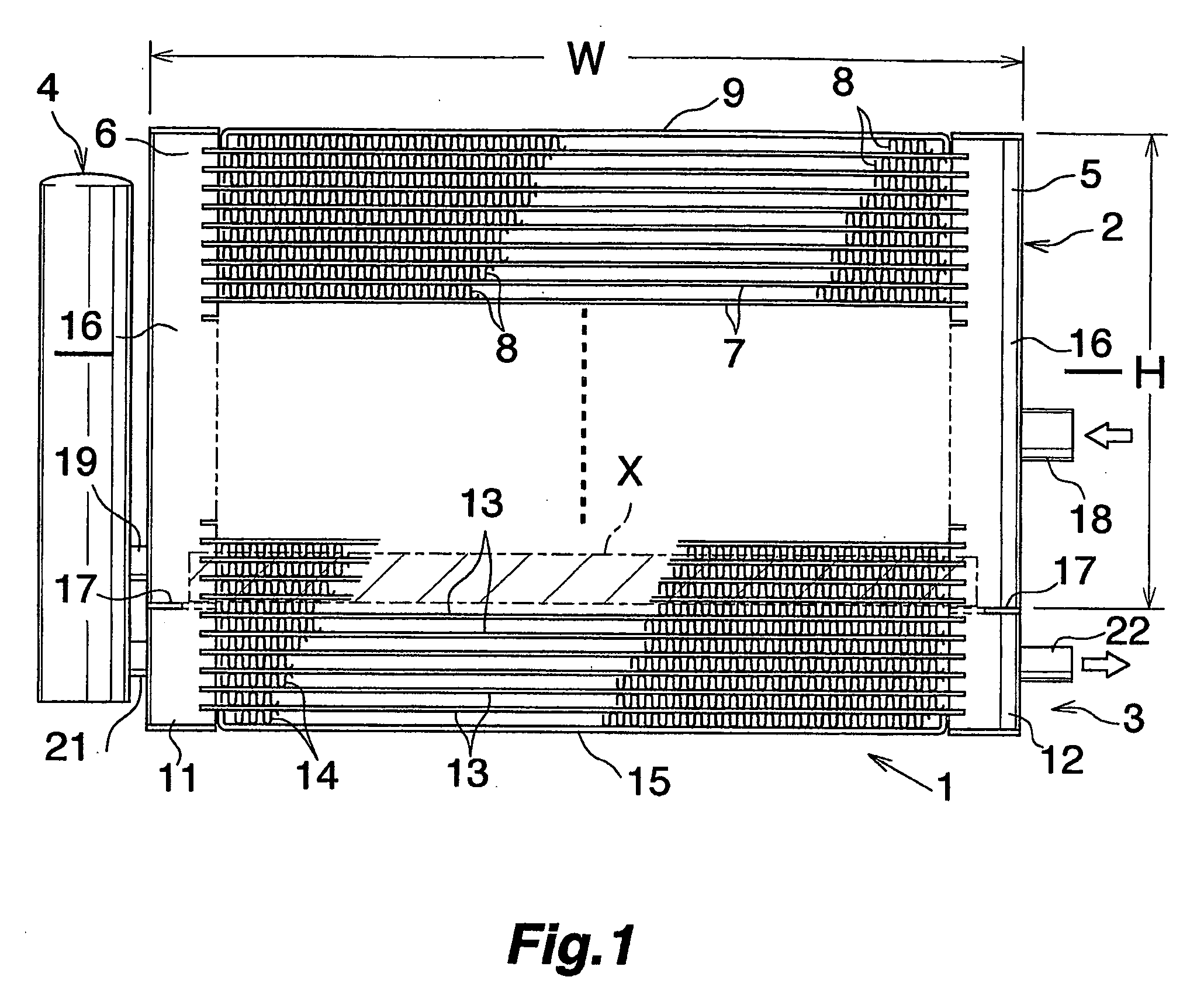
[0056]Used in this example was a heat exchanger 1 which was composed of a condenser portion 2 and a supercooler portion 3 having a combined overall height of 360 mm and an overall left-to-right width of 600 mm, and which was 300 mm in the height H of the condenser portion 2 and 43 in the total number of refrigerant tubes 7 of the condenser portion 2, 7 in the total number of refrigerant tubes 13 of the supercooler portion 3 and 21 in the number of refrigerant tubes 7 existing below the center, with respect to the vertical direction, of the refrigerant inlet 23 of the condenser portion 2 (see FIG. 1).

example 2

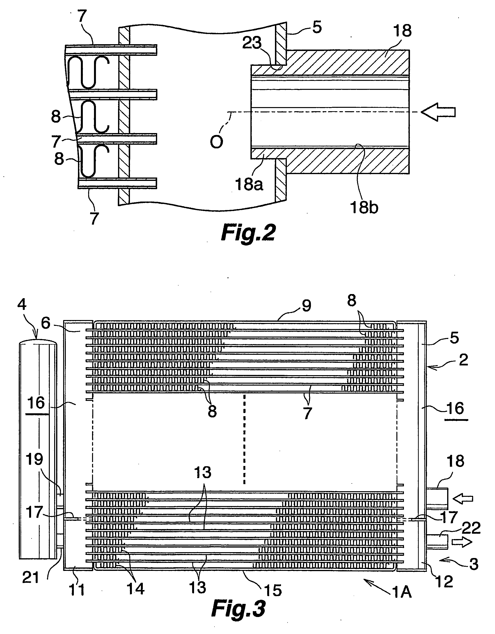
[0057]Used in this example was a heat exchanger 1A having the same construction as in Example 1 except that the condenser portion 2 had 7 refrigerant tubes 7 below the center O, with respect to the vertical direction, of the refrigerant inlet 23 (see FIG. 3).


PUM


Abstract

A condenser including an inlet header and an outlet header spaced apart from each other and extending vertically, a plurality of flat refrigerant tubes arranged one above another in parallel at a spacing between the two headers and jointed at opposite ends thereof to the respective headers, and fins between respective adjacent pairs of refrigerant tubes. The inlet header admits a refrigerant into interior thereof therethrough, and the outlet header causes the refrigerant to flow out therethrough. The refrigerant admitted into the inlet header flows through the refrigerant tubes toward the outlet header. The number of refrigerant tubes positioned below the center of the refrigerant inlet with respect to the vertical direction is up to 21, preferably up to 16, more preferably up to 7. The condenser can be prevented from becoming impaired in condensation performance when the refrigerant has a compressor lubricant incorporated therein.

Description

CROSS REFERENCE TO RELATED APPLICATIONS[0001]This application is an application filed under 35 U.S.C. §111(a) claiming the benefit pursuant to 35 U.S.C. §119(e)(1) of the filing date of Provisional Application No. 60 / 540,335 filed Feb. 2, 2004 pursuant to 35 U.S.C. §111(b).TECHNICAL FIELD[0002]The present invention relates to condensers, for example, for use in motor vehicle air conditioners which a rerefrigeration cycles to be installed in motor vehicles.[0003]In this description and the appended claims, the upper and lower sides and the left- and right-hand sides of the drawings will be referred to respectively as “upper,”“lower”, “left” and “right.”BACKGROUND ART[0004]Refrigeration cycles providing motor vehicle air conditioners have a compressor, condenser, pressure reducer (expansion valve) and evaporator. A gaseous refrigerant having a high temperature and high pressure and compressed by the compressor is condensed by the condenser to a liquid refrigerant, which is then expand...

Claims


Application Information

Patent Timeline
IPC IPC(8): F25B1/00F28F9/02F25B39/04F25B40/02F28D1/04F28D1/053
CPCF25B39/04F25B40/02F25B2339/044F28D2021/0084F28D1/0417F28D1/05375F25B2500/01
Inventor OGASAWARA, NOBORU
Owner SHOWA DENKO KK
Why Eureka
Try Eureka