Tufting Machine

a tufting machine and tufting technology, applied in the field of tufting machines, can solve the problems of high labor intensity, undesirable tufting machine of broadloom type, and restricted machine ability to tuft different colour areas,

Active Publication Date: 2009-07-09
PERPETUAL MACHINE CO
View PDF10 Cites 13 Cited by
  • Summary
  • Abstract
  • Description
  • Claims
  • Application Information

AI Technical Summary

Benefits of technology

[0026]The tufting needle may be mounted in the tufting mechanism in a manner that allows it to be rotated freely in either direction about its axis. The foot and needle may comprise inter-engaging formations so that the needle may be driven in rotation by the foot. The foot may be driven in rotation by any suitable mechanism.
[0027]It is an advantage of at least one embodiment of the invention that the pile height is able to be automatically changed on a vector by vector basis (or if the vectors are sufficient small, on a tuft by tuft basis). The effect of this is that loop pile areas can be a different pil

Problems solved by technology

It is for this reason that broadloom type multi-needle tufting machines are undesirable.
These machines are restricted in being able to tuft different colour areas since each needle is threaded with one specific colour for the entire deign and as the machine tufts row by row from bottom to top of the tuft, the tuft locations of each needle

Method used


Image

  • Tufting Machine
  • Tufting Machine
  • Tufting Machine

Examples


Embodiment Construction

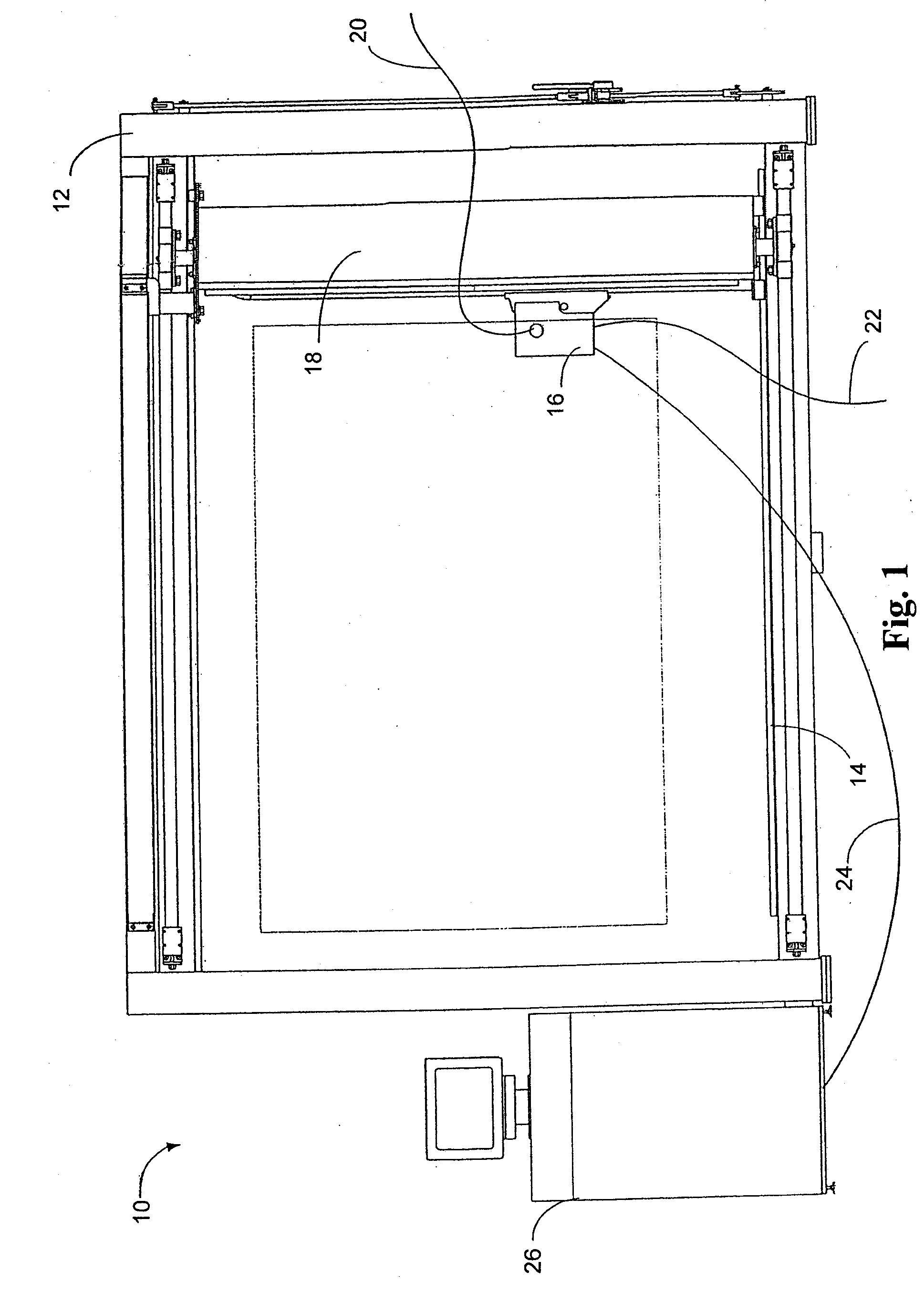
[0044]Referring first to FIG. 1 tufting machine 10 comprises a stand 12 onto which a stretch frame 14 can be mounted. In use, backing fabric is mounted on stretch frame 14. A tufting head 16 is also mounted on the stand in a movement system 18 that is able to translate in X- and Y-directions over the backing fabric. Yarn 20 is provided to the tufting head 16, as well as compressed air 22, electrical power and control signals 24. The control signals 24 are supplied from a computer-operated motion control system 26 which is operable under the control of a machine readable tufting design pattern comprising a series of vectors and associated control codes.

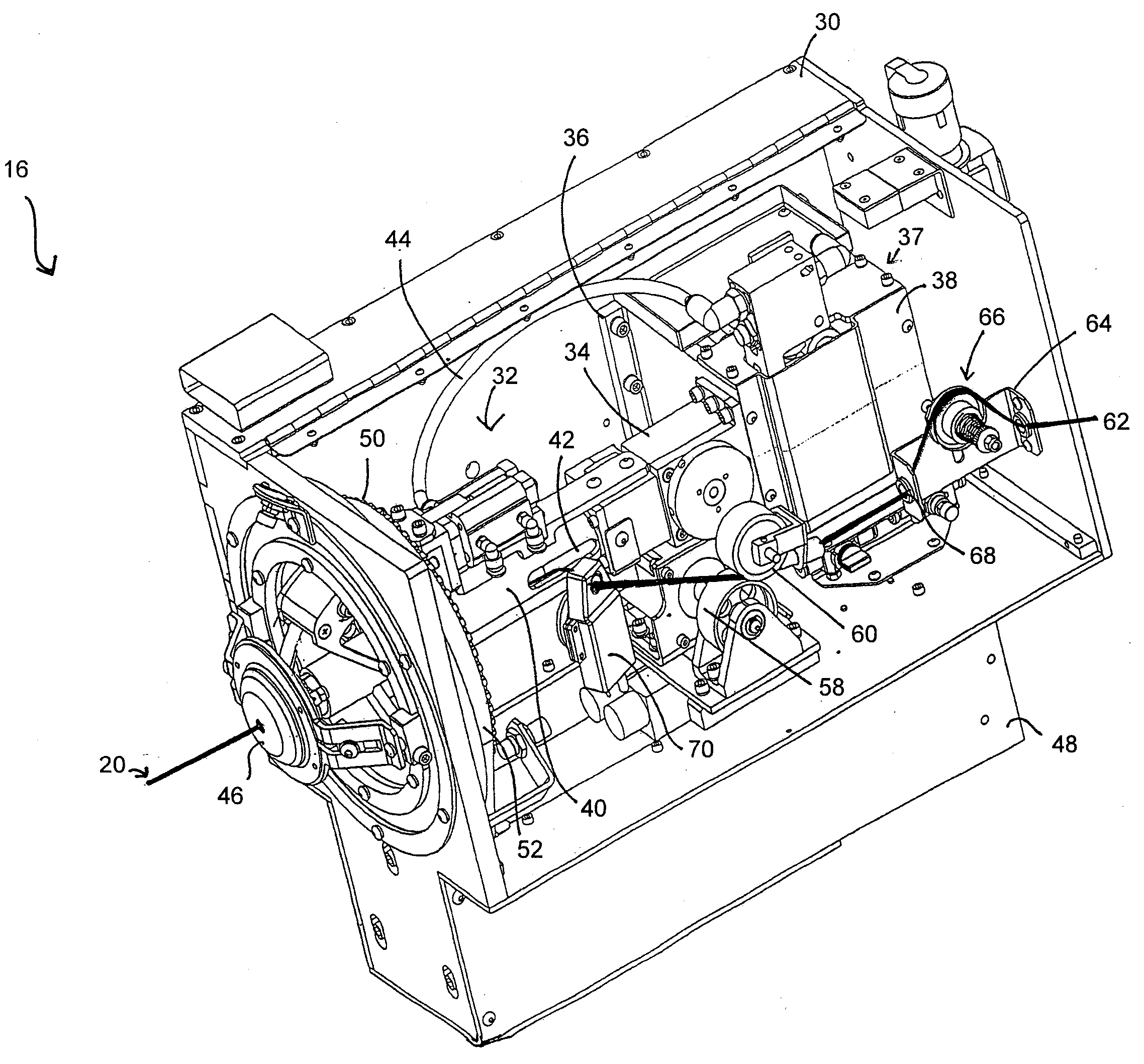
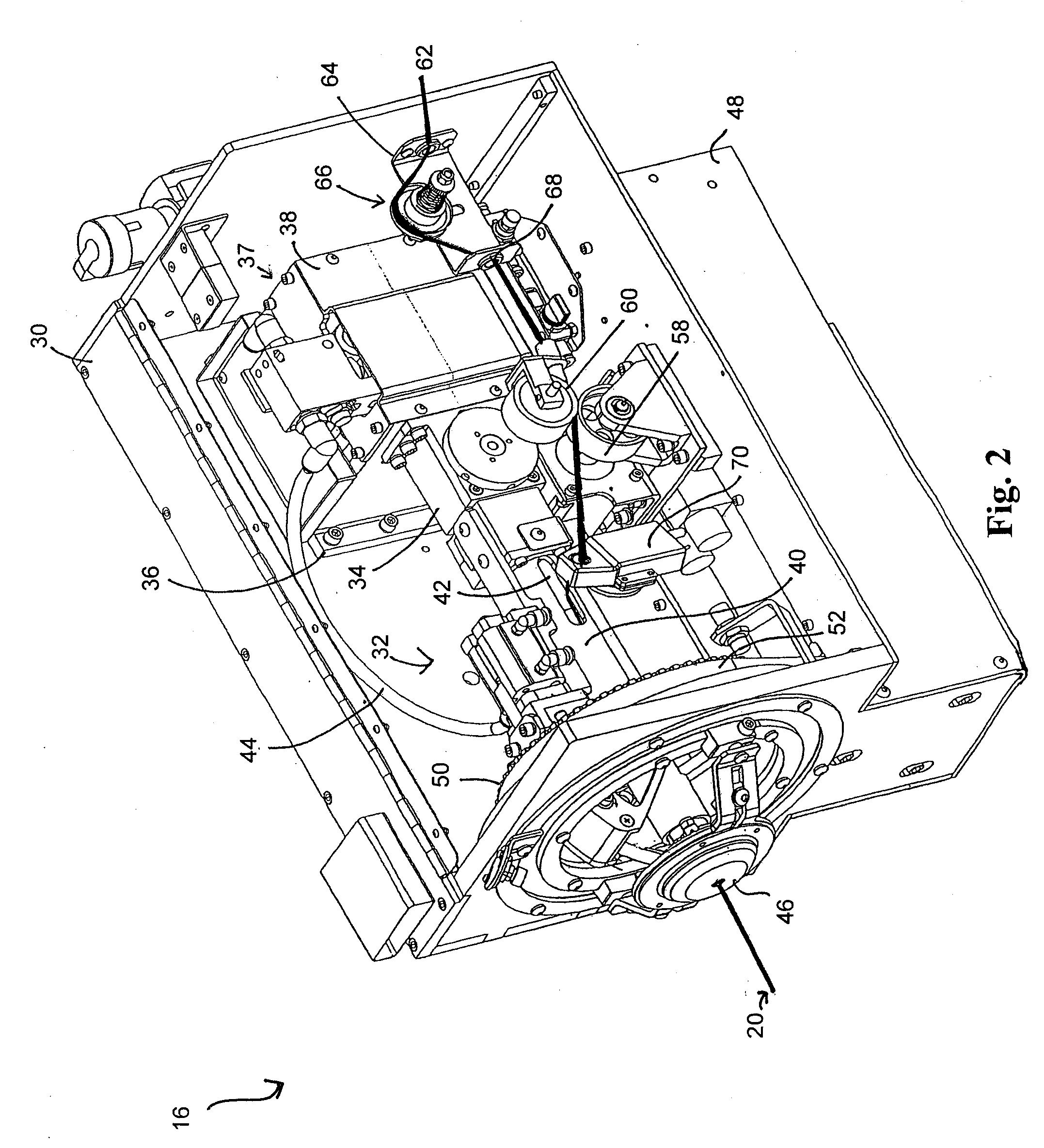
[0045]Referring to FIG. 2 the tufting head 16 comprises a frame 30 in which is mounted a tufting mechanism, indicated generally at 32. The tufting mechanism 32 has a gearbox 34 that is mounted to a motor mounting bracket 36 which holds an electric drive motor 37 in the frame 30. A tufting head barrel 40 extends forwardly from gearbox 3...


PUM


Abstract

The invention concerns an improved tufting machine which comprises a tufting head translatable within said tufting machine in X- and Y-directions with respect to backing fabric by means of a movement system. The tufting head comprises a tufting mechanism having a cyclic mode of operation, a hollow needle mounted in the tufting mechanism that is moveable relative to a cooperating foot in a reciprocating manner to insert a tuft of yam into backing fabric in each cycle, a yarn supply mechanism mounted in the tufting mechanism and operable to supply a length of yam to the hollow needle in each cycle, a yarn cutter mounted in the tufting head that is selectively operable to cut the length of yam in selected cycles to produce loop or cut pile, and a computer-operated motion control system.

Description

CROSS-REFERENCE TO RELATED APPLICATIONS[0001]The present application claims priority from Australian Provisional Patent Application No 2008900045 filed on 4 Jan. 2008, respectively, the contents of which are incorporated herein by reference.TECHNICAL FIELD[0002]This invention concerns improvements in the production of “hand tufted rugs”, carpets and wall hangings by using a “tufting gun”. A tufting gun employs a single hollow needle through which yarn is fed by high pressure air or by mechanical means, into a backing material, to form tufts of yarn, which tufts may be cut pile or loop pile. Such “tufting guns”, as in this invention, are controlled and guided automatically via a computer controlled tufting machine that uses vector based design definition to tuft a nominated three dimensional design in one or more yarn colours.BACKGROUND ART[0003]Textured effects in tufted rugs and carpets are created by the use of designs which intermingle cut pile and loop pile effects frequently. I...

Claims


Application Information

Patent Timeline
IPC IPC(8): D05C15/18
CPCD05C15/18D05C15/34D05C15/30D05C15/24
Inventor WILSON, WILLIAM BRIANJEZ, MILEVAN WOERKOM, JOSEPH
Owner PERPETUAL MACHINE CO
Why Eureka
Try Eureka