Method of printing and printer

Inactive Publication Date: 2009-07-09
DAINIPPON SCREEN MTG CO LTD
View PDF5 Cites 13 Cited by
  • Summary
  • Abstract
  • Description
  • Claims
  • Application Information

AI Technical Summary

Benefits of technology

[0007]The present invention is intended for a method of printing an image on an object

Problems solved by technology

It is considered that the clear ink is applied onto the whole image of the color inks like in the techniques of Documents 1, 2 and 4, however, it is difficult to apply the cl

Method used


Image

  • Method of printing and printer
  • Method of printing and printer
  • Method of printing and printer

Examples


Embodiment Construction

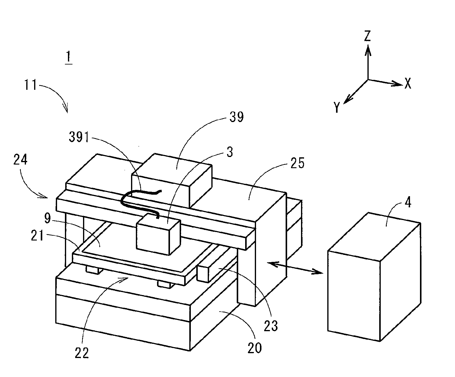
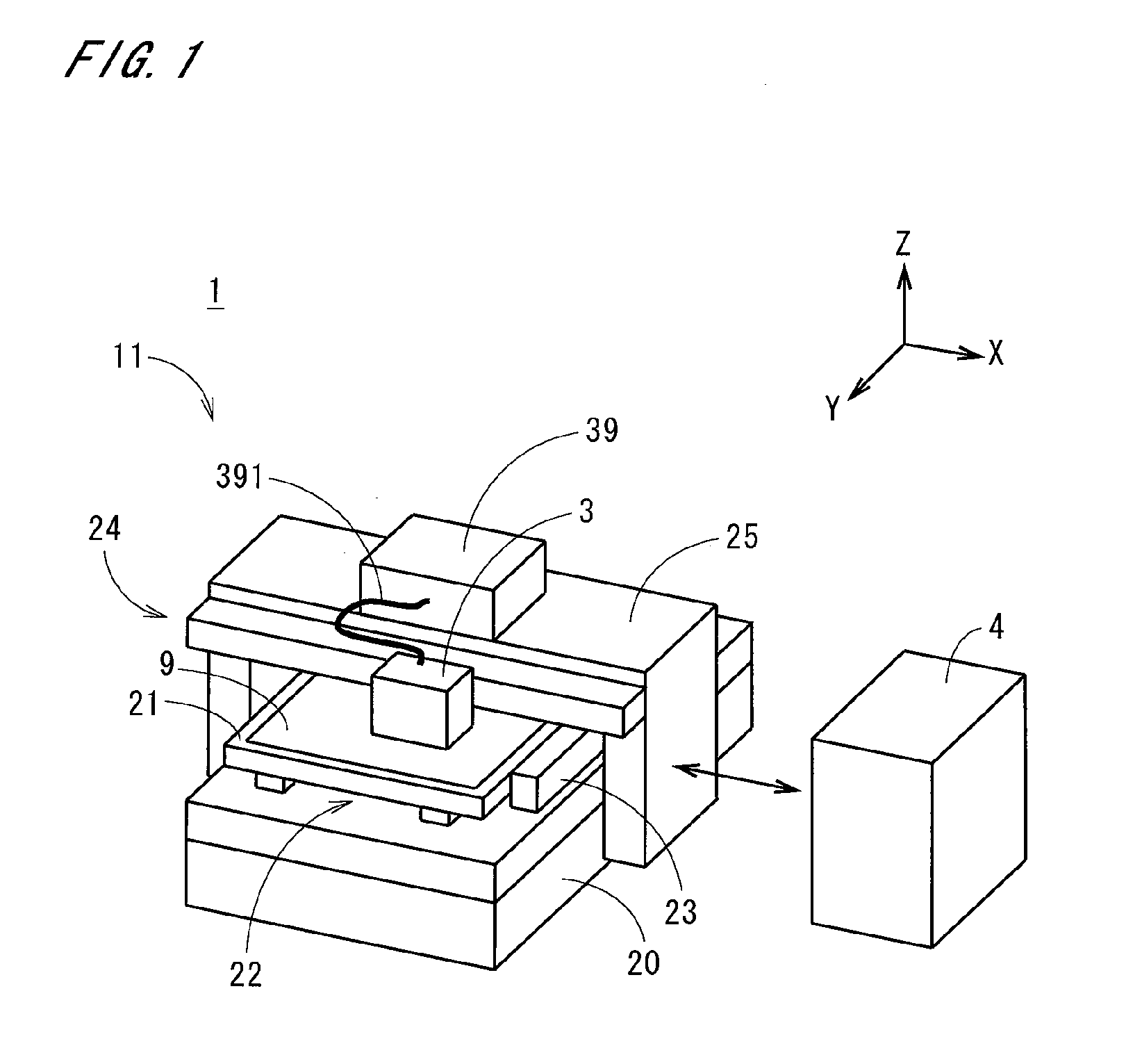
[0034]FIG. 1 is a perspective view showing an appearance of a printer 1 in accordance with a preferred embodiment of the present invention. The printer 1 performs printing in an inkjet manner on a plate-like or sheet-like base member 9 whose surface to be printed has liquid repellency (hydrophobicity).

[0035]The printer 1 of FIG. 1 has a main body 11 and a control part 4, and the main body 11 has a stage 21 for holding the base member 9 on a surface on the (+Z) side of FIG. 1 and a stage moving mechanism 22 which is provided on a base part 20. A nut of a ball screw mechanism of the stage moving mechanism 22 is fixed on a surface of the stage 21 which is opposite to the surface on which the base member 9 is held. By rotating a motor connected to the ball screw mechanism, the stage 21 smoothly moves in the Y direction (sub scan direction) of FIG. 1. A position detection module 23 for detecting a position of the stage 21 relative to the base part 20 is further provided on the base part ...


PUM


Abstract

In an inkjet printer, a halftone image is generated from a grayscale original image with using a first threshold matrix, and the halftone image is printed with color inks having light curability on a base member with liquid repellency. A tint image with a dot area rate 1 to 40% is generated with a second threshold matrix where the number of halftone dots defined in a unit area in an image generated with the second threshold matrix is smaller than that in an image generated with the first threshold matrix, and the tint image is printed with clear ink having light curability. On the base member, halftone dots of the clear ink are distributed according to the tint image, and relatively large projections and depressions are macroscopically uniformly formed with lessening small projections and depressions of the color inks, to acquire a printed matter with uniform gloss.

Description

BACKGROUND OF THE INVENTION[0001]1. Field of the Invention[0002]The present invention relates to a technique for printing an image on an object.[0003]2. Description of the Background Art[0004]In printing an original image of gray scale (i.e., continuous tone), an AM (Amplitude Modulated) screening where gray levels are represented by changing the size of halftone dots which are regularly arranged (accurately, a halftone dot is a cluster which is a group of dots (or pixels) connecting one another) and an FM (Frequency Modulated) screening where gray levels are represented by changing the number of halftone dots of certain size which are irregularly arranged (a halftone dot is a dot (or pixel) or a group of dots connecting one another), have been used. Actually, a threshold matrix where a plurality of elements are arranged in a row direction and a column direction and a threshold value is assigned to each element, is generated and prepared in advance, and the original image is compare...

Claims


Application Information

Patent Timeline
IPC IPC(8): G06K15/00
CPCB41J2/2114H04N1/54H04N1/4055B41J11/002B41J3/407B41J11/00214
Inventor ASAI, HIROSHI
Owner DAINIPPON SCREEN MTG CO LTD
Why Eureka
Try Eureka