Mobile wireless terminal device
a terminal device and wireless technology, applied in the direction of resonant antennas, substantially flat resonant elements, independent non-interacting antenna combinations, etc., can solve the problems of deteriorating antenna characteristics and achieve the effect of high antenna characteristics
- Summary
- Abstract
- Description
- Claims
- Application Information
AI Technical Summary
Benefits of technology
Problems solved by technology
Method used
Image

Examples
first embodiment
The First Embodiment
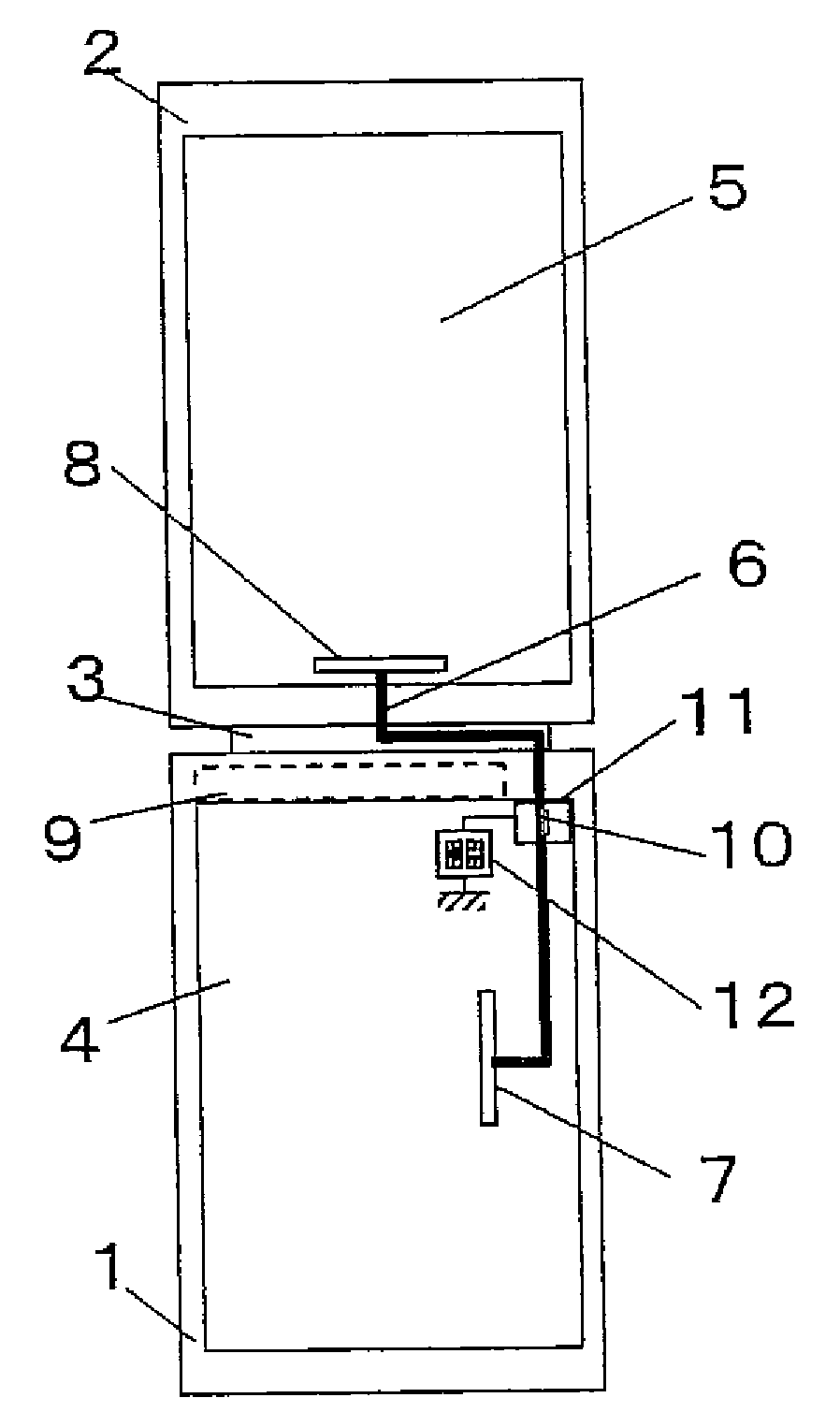
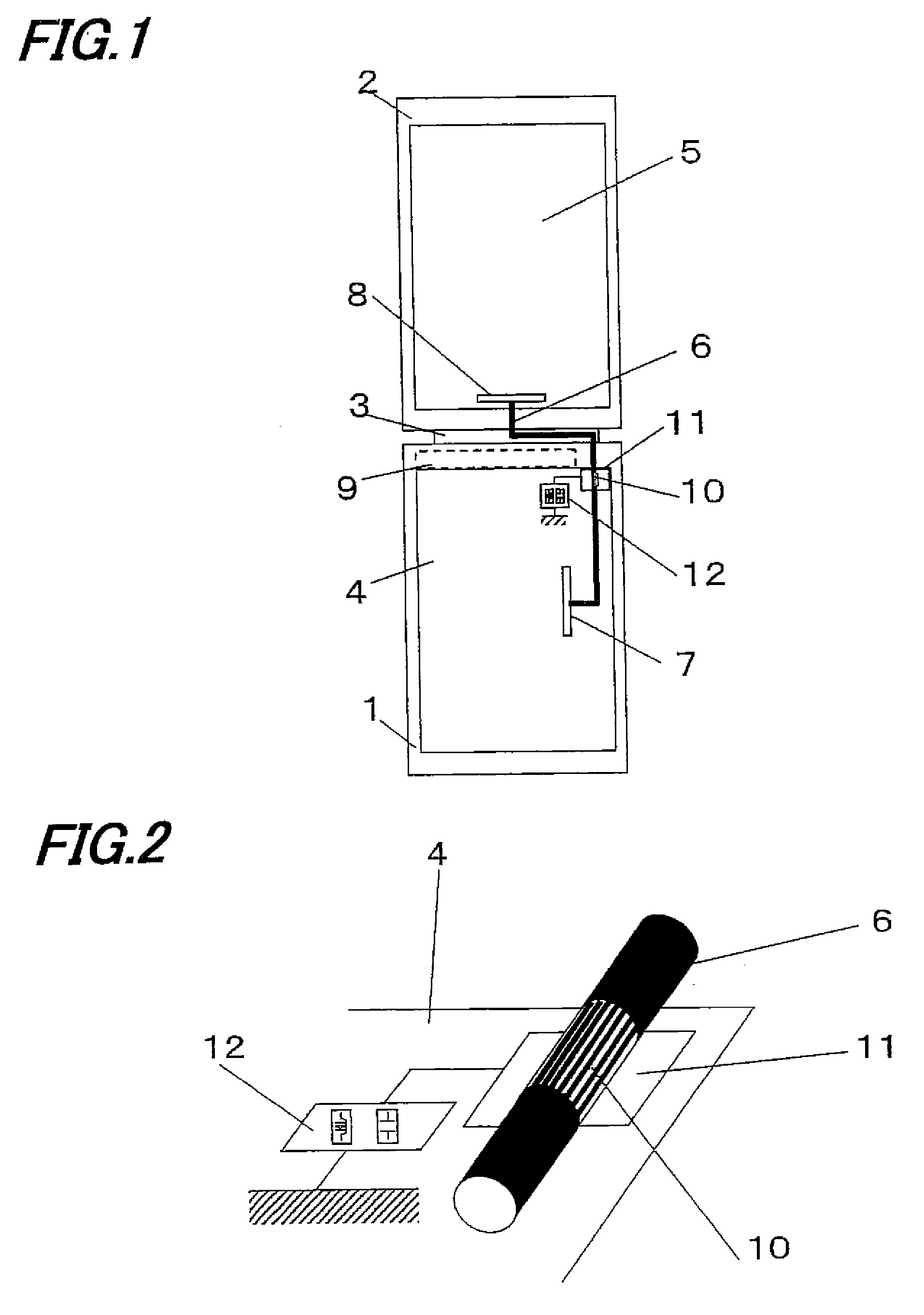
[0072]First, the first embodiment will be described with reference to the drawings. FIG. 1 is a schematic configuration view of a mobile telephone device in the present embodiment. The mobile telephone device is a folding-type mobile telephone device that has a first housing 1 and a second housing 2, which are connected by a coupling portion 3 for coupling in an openable / closable manner. Each of the first housing 1 and the second housing 2 has a first substrate 4 and a second substrate 5, and the first substrate 4 and the second substrate 5 are electrically connected at each of connector portions 7 and 8 by a thin wire coaxial cable 6.
[0073]The connector portion 7 is provided near the center portion of the first substrate 4, and the connector portion 8 is provided in the lower edge of the second substrate 5. The thin wire coaxial cable 6 is a coaxial cable group including a GND and a signal line, which are covered with an insulating material, except for the conne...
second embodiment
The Second Embodiment
[0082]Subsequently, the second embodiment will be described with reference to the drawings. First, FIG. 5 is a schematic configuration view of a mobile telephone device in the second embodiment. As shown in FIG. 5, in the second embodiment, the thin wire coaxial cable 6 has a metal-wrapped portion 13 through an insulating material. The metal-wrapped portion 13 is electrically connected to the GND of the first substrate 4 in the edge portion of the first substrate 4. Note that, if any part in other component configuration is same as in the first embodiment, same reference numeral is given thereto, with repeated description omitted.
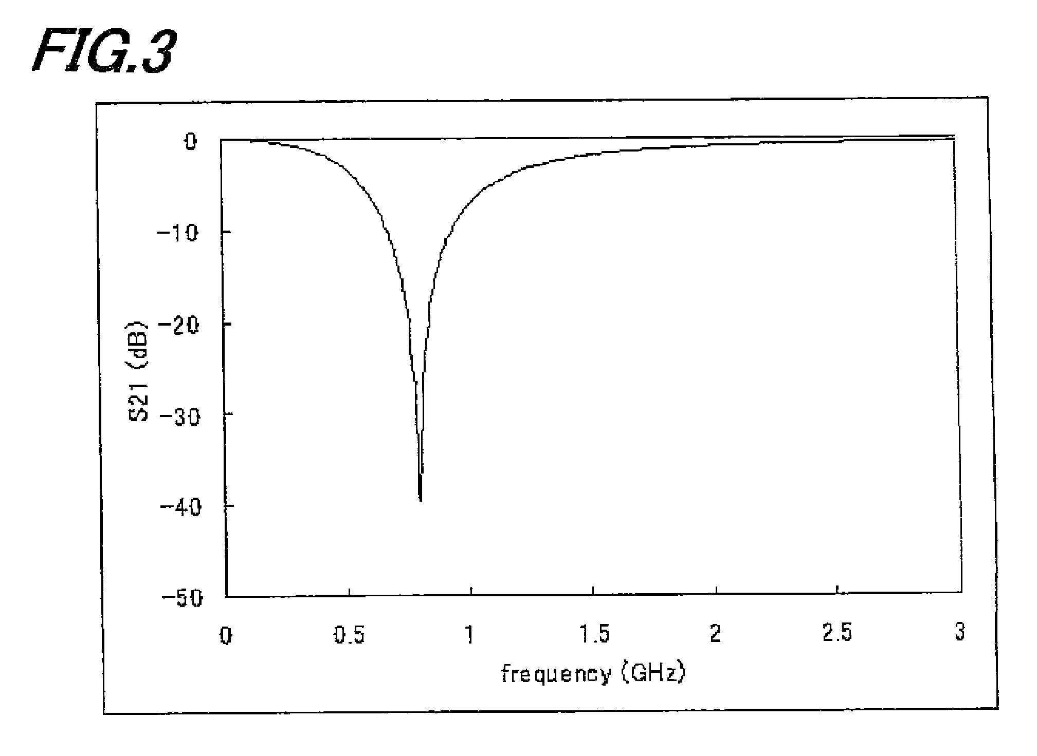
[0083]According to the configuration shown in FIG. 5, the GND in the thin wire coaxial cable and the metal metal-wrapped portion 13 are not electrically connected because of being through the insulating material, but connected in a high frequency manner by a capacitive coupling.
[0084]Therefore, as shown in FIG. 6, the GND in the thin wi...
third embodiment
The Third Embodiment
[0085]Subsequently, the third embodiment will be described with reference to the drawings. FIG. 7 is a schematic configurational view of a mobile telephone device in the third embodiment. Note that, if any part in other component configuration is same as in the first embodiment, same reference numeral is given thereto, with repeated description omitted.
[0086]The thin wire coaxial cable 6 has a first metal-wrapped portion 131 and a second metal-wrapped portion 132 that have different wrapping areas through the insulating material.
[0087]Regarding to the wrapping areas of the two metal-wrapped portions 131 and 132, the area of the metal-wrapped portion 131 is small, and the area of the metal-wrapped portion 132 is large. With this structure, the capacitive couplings are different in each of the metal-wrapped portions, and therefore the frequency characteristics of the impedance in each of the metal-wrapped portions are also different. The frequency characteristics i...
PUM
 Abstract
Description
Claims
Application Information
 - R&D
- Intellectual Property
- Life Sciences
- Materials
- Tech Scout
- Unparalleled Data Quality
- Higher Quality Content
- 60% Fewer Hallucinations
Browse by: Latest US Patents, China's latest patents, Technical Efficacy Thesaurus, Application Domain, Technology Topic, Popular Technical Reports.
© 2025 PatSnap. All rights reserved.Legal|Privacy policy|Modern Slavery Act Transparency Statement|Sitemap|About US| Contact US: help@patsnap.com