Eureka AIR delivers breakthrough ideas for toughest innovation challenges, trusted by R&D personnel around the world.

Method and apparatus for fluid pressure testing

Inactive Publication Date: 2009-07-16
THE WALLACE GROUP
View PDF7 Cites 4 Cited by
  • Summary
  • Abstract
  • Description
  • Claims
  • Application Information

AI Technical Summary

Benefits of technology

[0014]In one embodiment, a process for field testing an automatic air valve connected to a testing apparatus in fluid communication with an auxiliary valve situated at a pipeline system high point comprises closing the auxiliary valve, draining the testing apparatus, applying pressurized air to the testing apparatus, monitoring the testing apparatus, and determining whether the automatic air valve is releasing air.
[0015]In another embodiment, a process for field testing an automatic air valve connected to a testing apparatus in fluid communication with an auxiliary valve situated at a pipeline system high point comprises closing the auxiliary valve, draining the testing apparatus, applying pressuriz

Problems solved by technology

The operation of water and wastewater pipeline systems may be severely impacted by the presence of air trapped in the pipeline.
In fact, failure to properly de-aerate the line may lead to pump, valve, and pipe failures as well as faulty instrument readings.
This condition may lead to a host of problems in the pipeline, including line restriction, flow stoppage, or high pressure surge (water hammer).
In addition to the problem of trapped air in water and wastewater pipelines, vacuum or siphoning of the line may occur during a system shut down or failure.
Such a condition may lead to line collapse or intensified surges in the pipeline.
However, as important as these valves are to the proper functioning and life of water and wastewater pipeline systems, a shortage of apparatus and procedures exist for ensuring proper functioning of these valves in the field.

Method used


Image

  • Method and apparatus for fluid pressure testing
  • Method and apparatus for fluid pressure testing
  • Method and apparatus for fluid pressure testing

Examples


Embodiment Construction

[0025]The present invention generally relates to an apparatus and process for field testing the functioning of automatic air valves in water and wastewater pipeline systems.

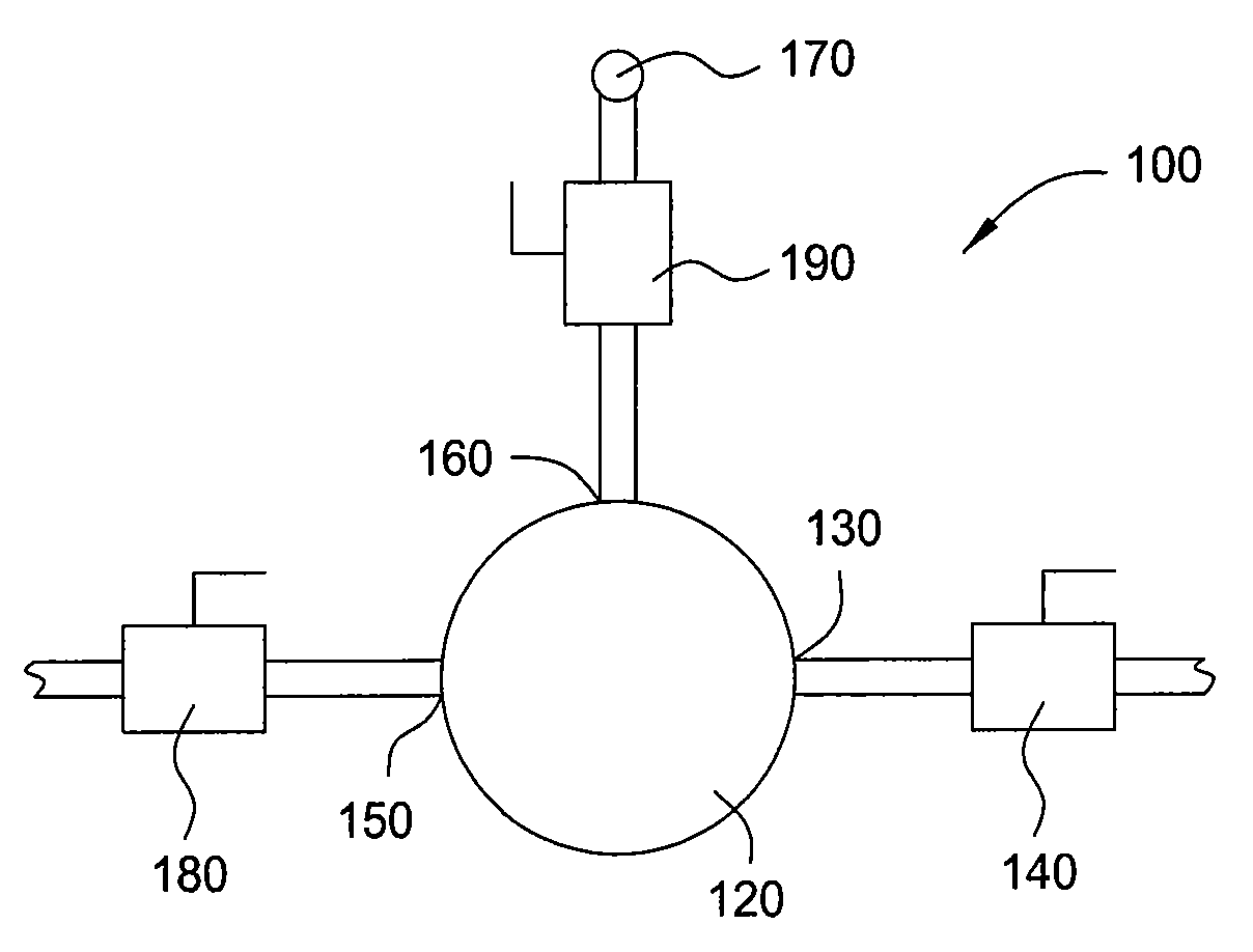
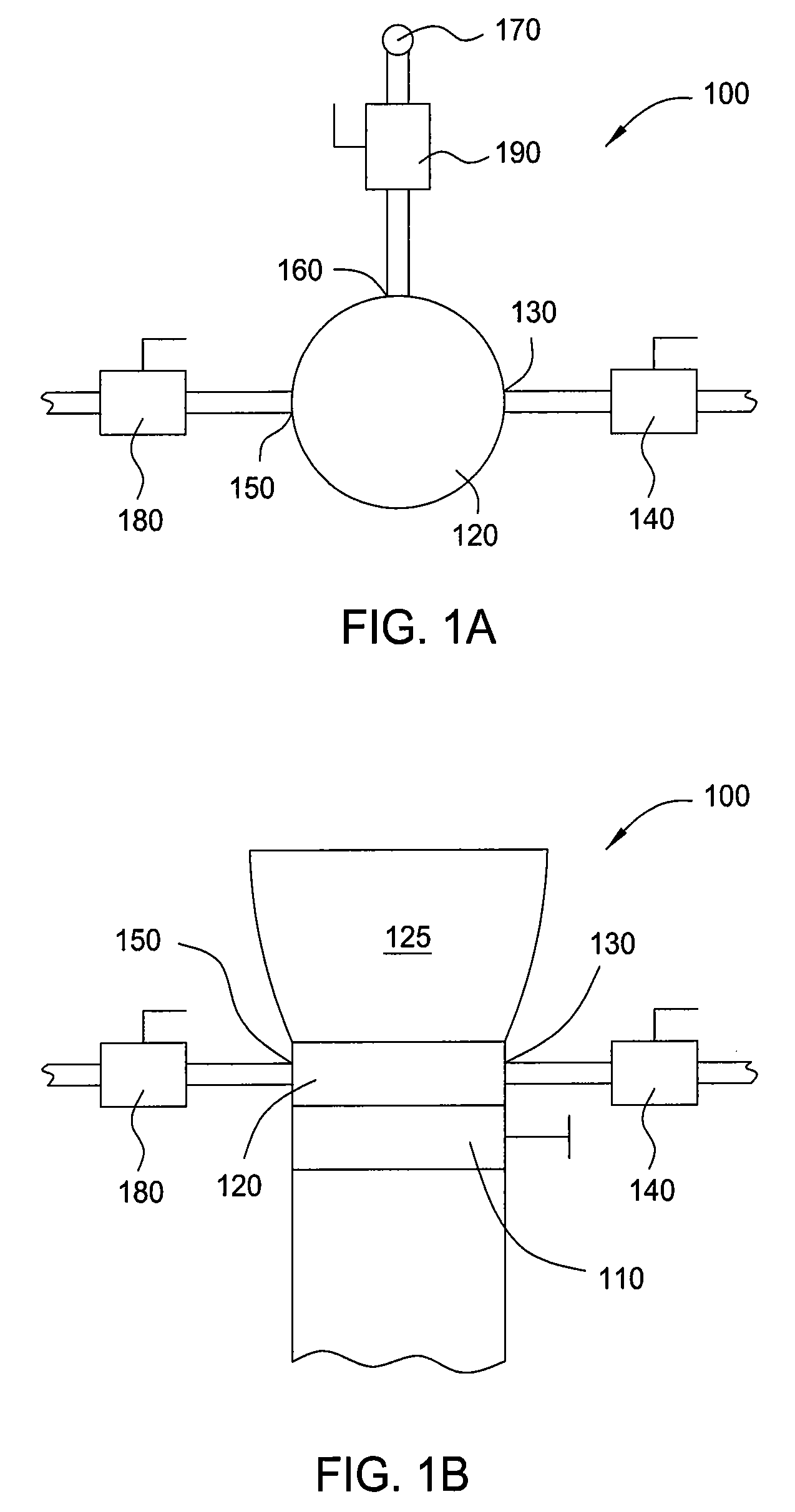
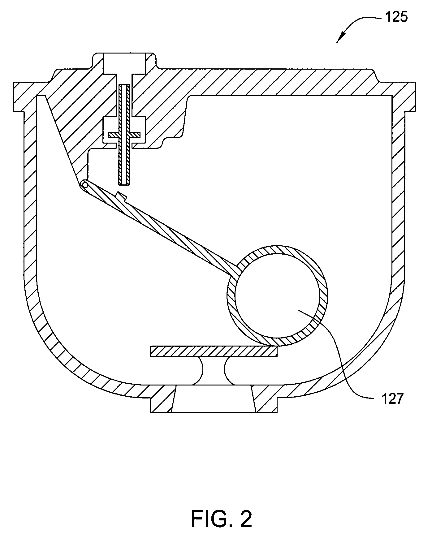
[0026]FIG. 1A is a schematic top view and FIG. 1B is a schematic front view of an embodiment of an apparatus 100 for field testing automatic air valves in water and wastewater pipeline systems. An auxiliary shut-off valve 110 may be positioned to extend from a pipeline system high point, where trapped air tends to accumulate. A test flange 120 may be positioned between auxiliary shut-off valve 110 and an automatic air valve 125 (omitted from FIG. 1A for clarity of other features of the invention). A cross-sectional, front view of an exemplary air valve 125 is shown in FIG. 1C. The automatic air valve 125 may have a float component 127 for closing and opening the air and / or vacuum release portion of air valve 125. The automatic air valve 125 may be an air / vacuum valve, an air relief valve, a combination air valve,...


PUM


Abstract

A method and apparatus for testing the functionality of automatic air valves positioned at high points of a pipeline system are provided. The invention generally provides a testing flange and a process for performing various fluid pressure tests to determine whether automatic air valves are properly releasing and / or stabilizing air within a pipeline system.

Description

BACKGROUND OF THE INVENTION[0001]1. Field of the Invention[0002]Embodiments of the present invention generally relate to an apparatus and process for field testing automatic air valves in water and wastewater pipeline systems.[0003]2. Description of the Related Art[0004]The operation of water and wastewater pipeline systems may be severely impacted by the presence of air trapped in the pipeline. In fact, failure to properly de-aerate the line may lead to pump, valve, and pipe failures as well as faulty instrument readings.[0005]Air in a pressurized, operating pipeline comes from three primary sources: air initially present in the line prior to startup, air or gas contained or generated within the water or wastewater itself, and air that enters the line through mechanical equipment.[0006]Regardless of the source, the air present in the line tends to accumulate at high points in the line. This condition may lead to a host of problems in the pipeline, including line restriction, flow s...

Claims


Application Information

Patent Timeline
IPC IPC(8): G01L27/00
CPCG01M3/2876
Inventor KUHNLE, CARLMONTEITH, DAVIDWALLACE, R.E.GARRETT, JR., JESSIE L.
Owner THE WALLACE GROUP
Why Eureka
Eureka Blog
Learn More