Hinged radar arch for marine vessels

a radar arch and arch technology, applied in special-purpose vessels, vessel construction, transportation and packaging, etc., can solve the problems of inferior construction, side-to-side vibration of radar arch, and insufficient rigidity and stability of conventional high arches laterally

Active Publication Date: 2009-07-16
XTREME MARINE CORP
View PDF9 Cites 21 Cited by
  • Summary
  • Abstract
  • Description
  • Claims
  • Application Information

AI Technical Summary

Benefits of technology

[0013]Also provided is an anchoring subassembly provided adjacent to an aft edge region of the basal edge for releasably securing the arch assembly to the boat.

Problems solved by technology

Conventional high arches may not be sufficiently rigid and stable laterally.
In rough seas, boat-to-wave impacts—especially at higher boat speeds—such arches may tend to result in vibration of the radar arch from side to side—“racking”.
This racking has several adverse consequences.
This may be viewed by the maritimer as inferior construction.
Additionally, boat equipment mounted on and within the radar arch may suffer from excessive shaking.
The radar transmitter mounted atop the radar thus may be most detrimentally affected as a result of the vibration.
Moreover, should the racking of the radar arch become excessive and last for a sufficient amount of time, portions of the radar arch may begin to crack and fail.

Method used


Image

  • Hinged radar arch for marine vessels
  • Hinged radar arch for marine vessels
  • Hinged radar arch for marine vessels

Examples


Embodiment Construction

)

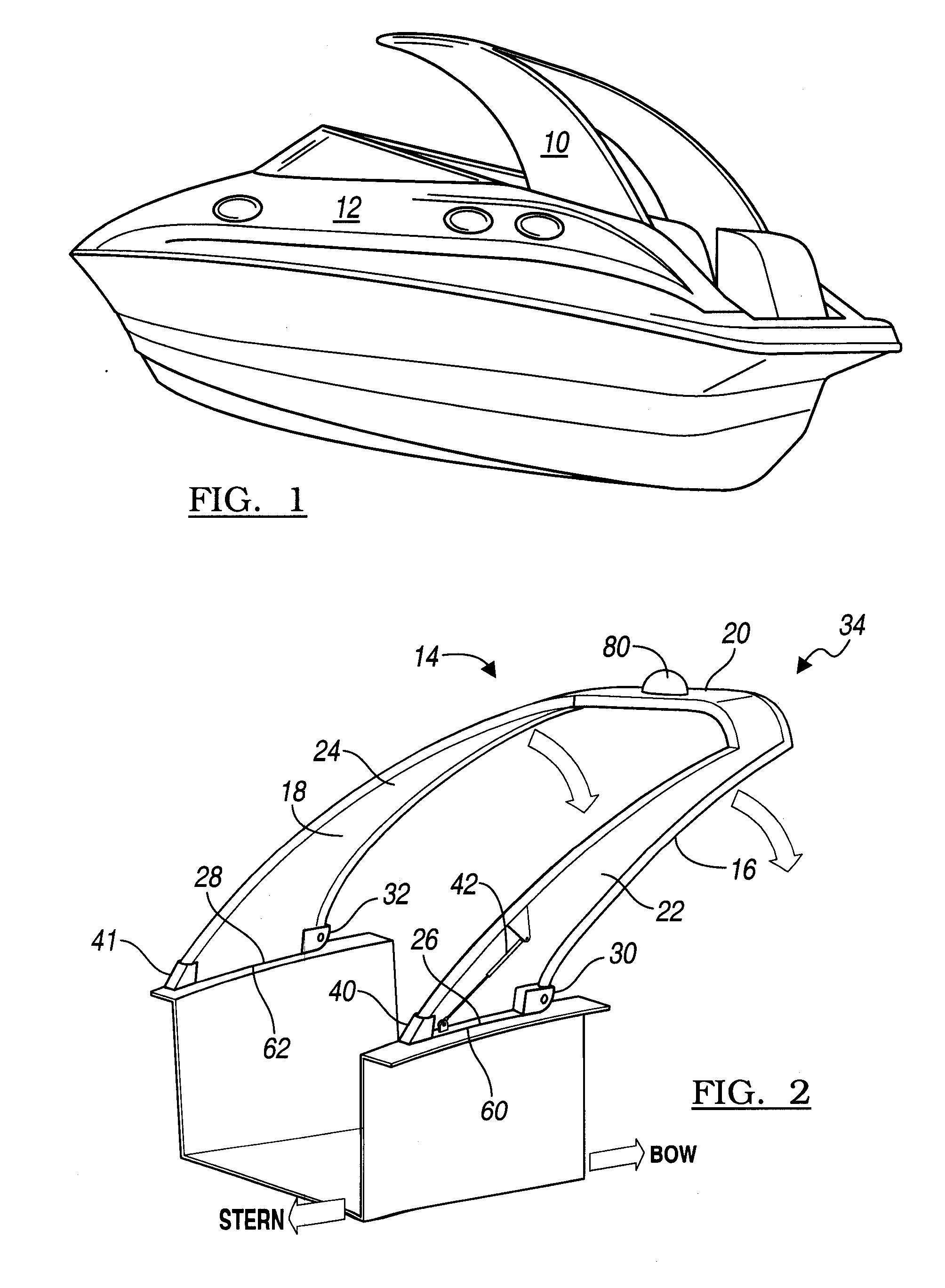
[0020]FIG. 1 depicts an arch assembly 10 that is pivotably mounted on a boat 12. In the configuration shown, the arch assembly 10 extends forwardly toward the bow of the boat, but the invention is not so limited. In some embodiments, the arch assembly 10 may tilt rearwardly toward the stern of the boat. Optionally, at least part of the arch assembly 10 is hollow.

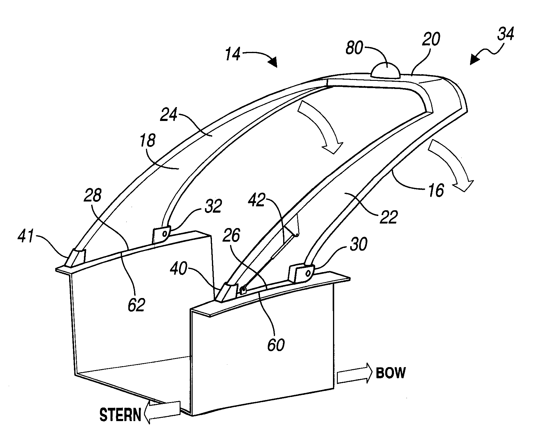
[0021]Turning now to FIG. 2, there is depicted additional detail of one embodiment of the arch assembly 10. As shown, an arch structure 14 is defined as a generally inverted U-shaped configuration. In FIG. 2, for orientation, it is assumed that the bow of the boat lies on the right hand side, and the stern toward the left hand side of FIG. 2. With that frame of reference, the arch 14 has a forward edge region 16 and an aft edge region 18.

[0022]The configuration of the arch 14 includes a laterally extending top portion 20 that generally span across most, if not all, of the width of the boat. A pair of downwardly extending le...


PUM


Abstract

An arch assembly 10 for pivotably mounting on a boat 12, its method of manufacture, and deployment in use. The assembly 10 has an arch 14 with a generally inverted U-shaped configuration, a forward edge region 16 and an aft edge region 18, a laterally extending top portion 20 generally spanning the width of the boat 12 and a pair of downwardly extending leg portions 22, 24 for connection to the boat 12. Each leg portion 22, 24 has a lower basal edge 26, 28. A knuckle joint 30, 32 is provided adjacent to an edge region of the basal edge 26, 28 about which the arch assembly 10 may pivot from a secured upright position through intermediate positions 36 to an extended lower position 38 through a number (R) degrees of arcuate displacement. An anchoring subassembly 40, 41 provided adjacent to another region of the basal edge 26, 28 for releasably securing the arch assembly 10 to the boat 12. Means for influencing 42 pivotable movement 43 of the arch assembly 10 as it moves arcuately are also provided.

Description

BACKGROUND OF THE INVENTION[0001]1. Field of the Invention[0002]This invention relates generally to radar arches for marine vessels.[0003]2. Background Art[0004]Radar arches are often deployed on marine vessels. In use, such arches not only provide a mount for radar, but also for supporting a number of other devices and accessories. They include, for example, dinghy davits, a flag pole, TV antenna, loran antenna, transom light, wind generator, solar panel, backup VHF antenna, GPS antenna, and attachment points for a sunshade.[0005]Preferably, from a visual viewpoint, the design of a radar arch should complement the lines of the boat, for example, by providing a curvature to the top of the arch and legs which support the arch in order to complement the transom and cabin lines. In some cases, the radar arch is anchored into the stern pulpit for additional stiffness. Conventionally, notably in fiberglass structures, stiffness has been provided by combining the stern pulpit and radar ar...

Claims


Application Information

Patent Timeline
Patent Type & Authority Applications(United States)
IPC IPC(8): B63B17/00
CPCB63B15/00B63B2015/0058B63B17/02B63B17/00
Inventor MCKEAND, SCOTT J.
Owner XTREME MARINE CORP
Why Eureka
Try Eureka