Biomimetic micro-aerial-vehicle with figure-eight flapping trajectory

a technology of flying vehicle and micro-aerial vehicle, which is applied in the field of flying vehicle of micro-aerial vehicle, can solve the problems of increasing product weight, complex installation and maintenance, and limiting the miniaturization of an ornithopter or micro-aerial vehicl

Active Publication Date: 2009-07-16
TAMKANG UNIVERSITY
View PDF8 Cites 33 Cited by
  • Summary
  • Abstract
  • Description
  • Claims
  • Application Information

AI Technical Summary

Benefits of technology

[0006]The object of the present invention is to provide a micro aerial vehicle including: a fuselage; a flapping transmission mechanism mounted on a front portion of the fuselage; a flexible wing frame secured to and driven by the flapping transmission mechanism for producing a figure-eight flapping trajectory for mimicking the flight of a tiny natural flier, such as hummingbird; and a tail wing secured to a tail portion of the fuselage; wherein the flexible wing frame is formed by respectively pivotally or rotatably mounting a wing skin made of parylene foil to a pair of leading-edge arm members made of carbon fiber, and linked to the flapping transmission mechanism so as to produce a miniaturized micro aerial vehicle.

Problems solved by technology

However, this prior art has the following drawbacks:1. Two motors and two gear boxes are required for driving the pairs of wings to increase the total weight of the ornithopter, thereby limiting the miniaturization of an ornithopter or micro-aerial-vehicle (MAV).2. A pair of wing movements (72, 74) are provided each having a pair of wings (76, 78; 80, 82), so that total four wings are required for constructing such an ornithopter, thereby possibly increasing product weight, installation complexity and maintenance problems.

Method used


Image

  • Biomimetic micro-aerial-vehicle with figure-eight flapping trajectory
  • Biomimetic micro-aerial-vehicle with figure-eight flapping trajectory
  • Biomimetic micro-aerial-vehicle with figure-eight flapping trajectory

Examples


Embodiment Construction

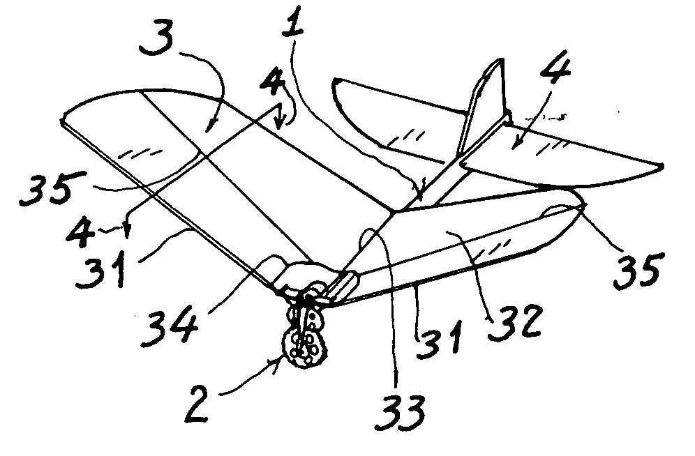
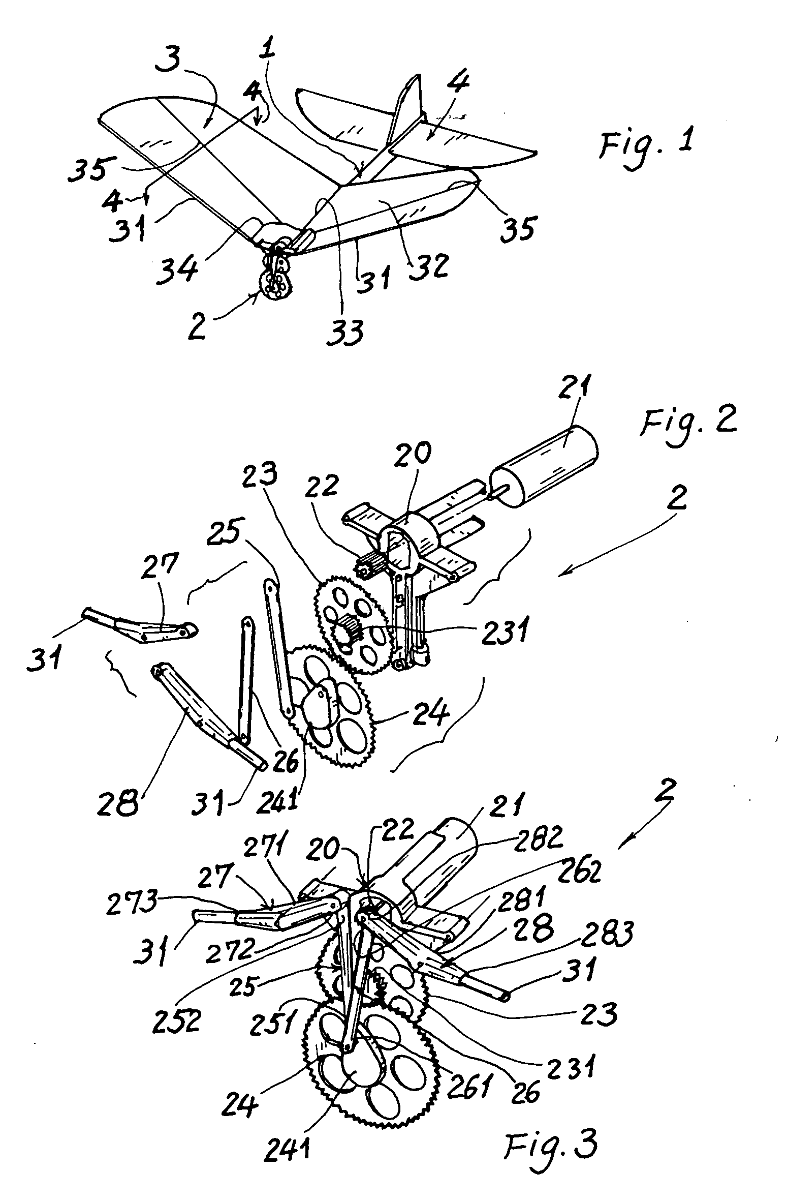
[0014]As shown in FIGS. 1-5, the micro aerial vehicle (or micro air vehicle, MAV) of the present invention comprises: a fuselage 1, a flapping transmission mechanism 2 mounted on a front portion of the fuselage 1, a flexible wing frame 3 pivotally secured to the flapping transmission mechanism 2, and a tail wing 4 mounted on a tail portion of the fuselage 1.

[0015]The fuselage 1 may simply be a longitudinal beam or rod made of light material, such as carbon fiber, aluminum or titanium alloy, or a light plastic material, not limited in the present invention.

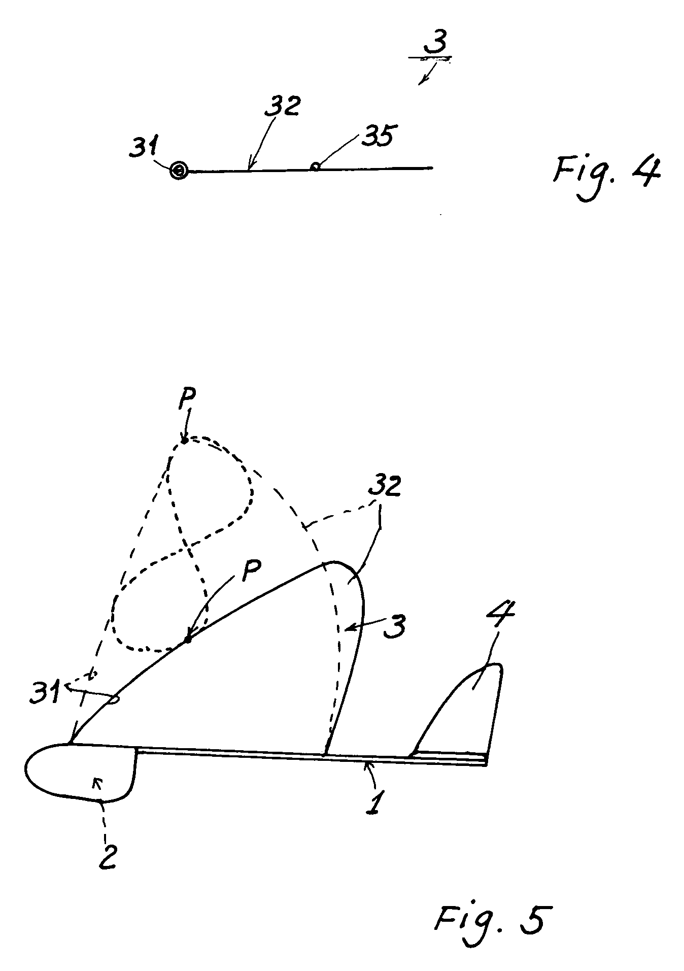
[0016]The flapping transmission mechanism (or flapping means) 2 may be formed as one degree-of-freedom (DOF) flapping movement, and is mounted on the front portion of the fuselage 1 and positioned under the flexible wing frame 3 for driving the flexible wing frame 3 for producing a figure-eight trajectory at a wing tip of the flexible wing frame 3 for rendering the thrust and lift of the micro aerial vehicle of the present inventio...


PUM


Abstract

A micro aerial vehicle includes: a fuselage; a flapping transmission mechanism mounted on a front portion of the fuselage; a flexible wing frame secured to and driven by the flapping transmission mechanism for producing a figure-eight flapping trajectory for mimicking the flight of a tiny natural flier, such as hummingbird; and a tail wing secured to a tail portion of the fuselage; wherein the flexible wing frame is formed by respectively pivotally or rotatably mounting a wing skin made of parylene foil to a pair of leading-edge arm members made of carbon fiber, and linked to the flapping transmission mechanism to thereby make a miniaturized micro aerial vehicle.

Description

BACKGROUND OF THE INVENTION [0001]U.S. Pat. No. 6,227,483 disclosed a wing movement for ornithopters including a plurality of pairs of wings mounted to the output shafts and each movable along a curved infinity-symbol-like pattern projecting substantially along one side of the drive motor.[0002]However, this prior art has the following drawbacks:[0003]1. Two motors and two gear boxes are required for driving the pairs of wings to increase the total weight of the ornithopter, thereby limiting the miniaturization of an ornithopter or micro-aerial-vehicle (MAV).[0004]2. A pair of wing movements (72, 74) are provided each having a pair of wings (76, 78; 80, 82), so that total four wings are required for constructing such an ornithopter, thereby possibly increasing product weight, installation complexity and maintenance problems.[0005]The present inventor has found the drawbacks of the prior art and invented the present micro aerial vehicle with lighter and simpler construction.SUMMARY O...

Claims


Application Information

Patent Timeline
Patent Type & Authority Applications(United States)
IPC IPC(8): B64C33/02
CPCA63F2009/2482A63H27/008A63F2009/2492
Inventor YANG, LUNG-JIEH
Owner TAMKANG UNIVERSITY
Why Eureka
Try Eureka