
Guide element for the passage of pipes, cables or the like through a wall

Inactive Publication Date: 2009-07-16
ULTRAFLEX
View PDF2 Cites 5 Cited by
  • Summary
  • Abstract
  • Description
  • Claims
  • Application Information

AI Technical Summary

Benefits of technology

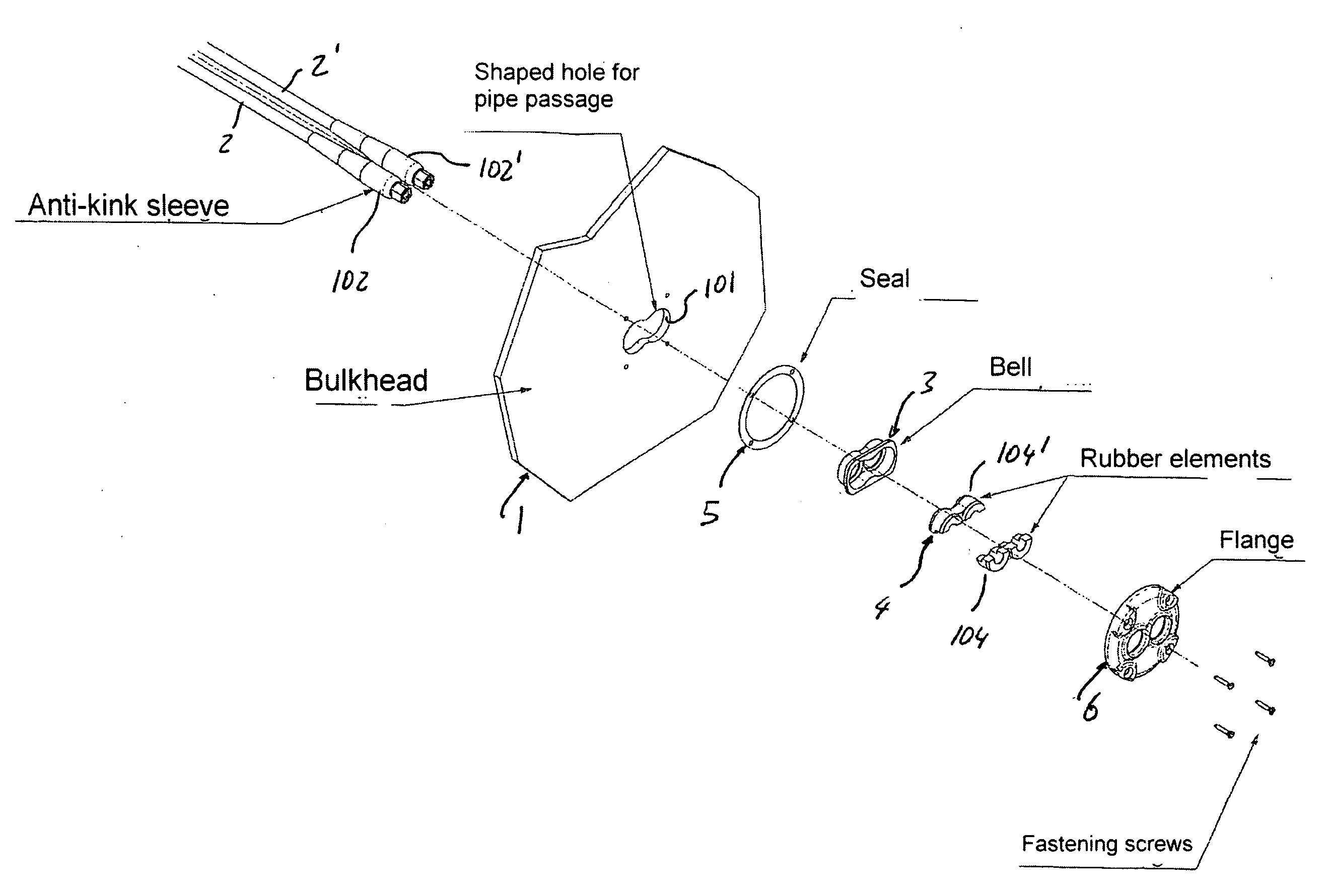
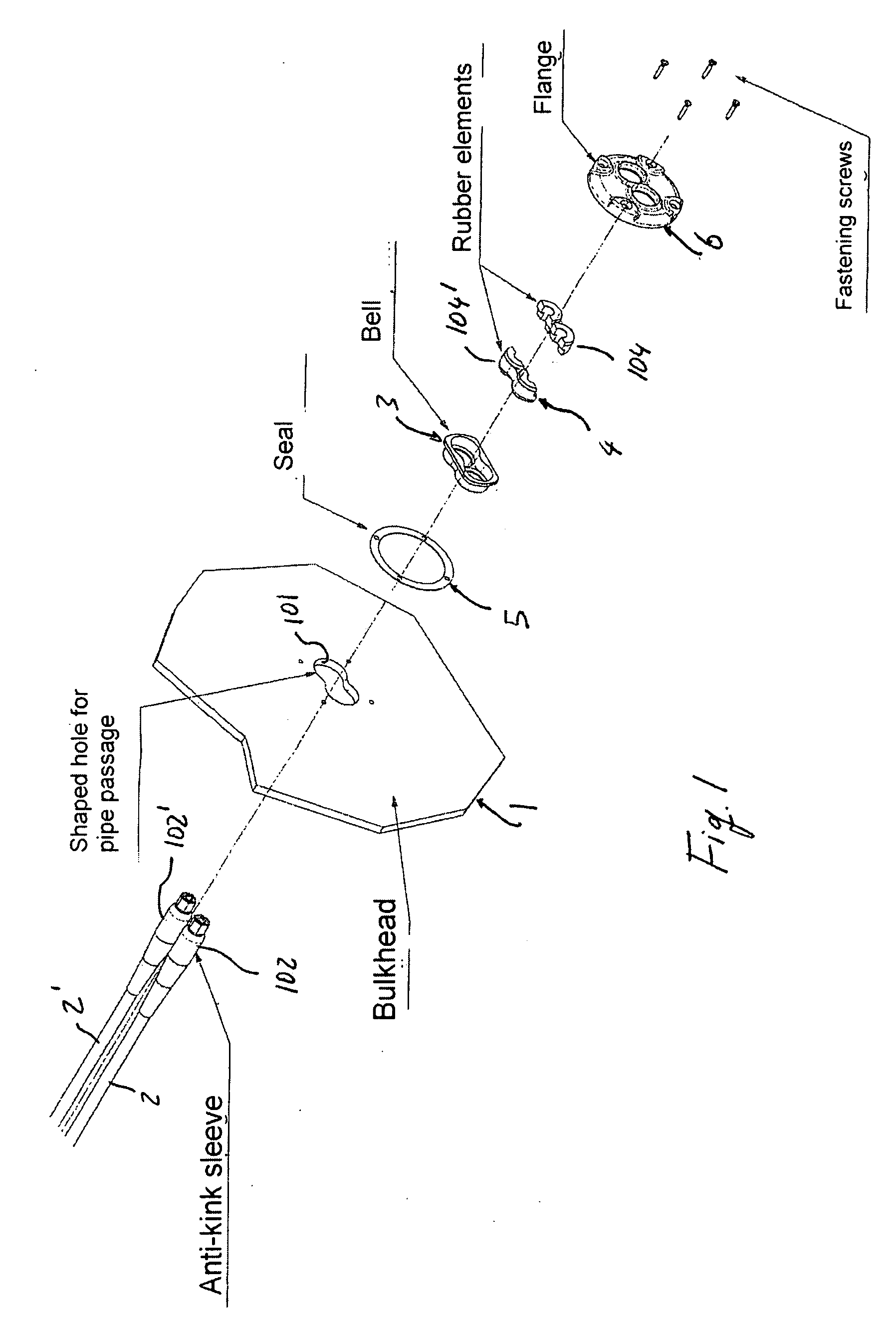
[0033]Another advantage of the invention is that locking action of the pipe or pipes and the sealing effect is performed by the elastic wedging part, i.e. the elastic wedging seal, at only one side of the wall or bulkhead between the cup-like part (also identified as cap or bell) and the pipes, while the sealing effect between the interposition element and the wall is achieved by a seal placed between the wall or bulkhead and the ring, and / or between the interposition element, i.e. the peripheral flange of the cup-like part and the wall strip surrounding the opening provided in the bulkhead. This seal is clamped to provide a seal between the ring and the wall and / or between the interposition element and the wall when the ring is clamped against the interposition element and against the wall.
[0034]One of the advantages of the invention is that one or more pipes are sealingly locked to provide protection against warping, kinking and possibly rupture with mass produced structural parts and at the same time with a precision of shape and size that optimally adjusts the locking force and elasticity exerted on the one or more pipe or pipes. The interposition element, in particular, only the rigid cup-like part, is simply fastened to the bulkhead, without causing additional stresses between the interposition element and pipes. At the same time, the opening in the bulkhead need not be dimensioned with the greatest precision, therefore, dimensional tolerances of the aperture in the bulkhead can be kept relatively high while providing full functionality of the element locking the one or more pipes reducing concerns about the quality level of the aperture in the bulkhead and the ability and possible errors of the person handling installation. Therefore, the present invention eliminates variables related to the manual ability of the installing technician and high repeatability of the installation procedure.
[0035]In an embodiment of the invention, the elastic wedging part of the interposition element is provided as a pair of bushings made of an elastic material, each coinciding and coaxial with one of the two openings provided in the cup-like part and each one having an axial extension slightly greater than the depth of the corresponding recess of the cup-like part. Further, each one of these bushings is provided with a coaxial narrowing portion at an intermediate area of the axial extension. This narrowing portion has is shorter than the entire axial extension of the bushing and it is connected by a conical flare to the inner cylindrical surface of the bushing.
[0036]In an embodiment of the invention, a crown of one or more axial recesses is provided at least at the end side of the elastic wedging part that is faced toward the direction of introduction into the cup-like part. These axial recesses extend for at least a portion of the total axial length of the elastic wedging part and are provided within the radial thickness of the wall surrounding each of the openings housing a pipe. This arrangement enables a saving in materials but also an adjustment of the elastic behavior of the wedging part in the direction of radial compression through the locking element.
[0037]In an embodiment of the invention, the cup-like part of the interposition element includes a perimetric flange overlapping or abutting against the wall strip surrounding the passage opening in the bulkhead, and an interposition seal between such flange and wall strip. The seal may become sealingly and automatically clamped at the same time as when the ring or fastening flange is clamped against the interposition element.
[0038]In an embodiment of the invention, the elastic wedging part includes an axial projecting part shaped like a pair of elastic projection sleeves on the side opposite to the bottom wall of the cup-like part. Such sleeves extend from the wedging element and are disposed side by side coaxially with one of the openings of the elastic wedging part and one of the openings in the bottom wall of the bell. Said projection sleeves overlap, for a certain axial length, the portion of a corresponding pipe locked into the interposition element.

Problems solved by technology

Because these types of pipes are typically, made of soft metal materials such as copper, these materials may cause the pipes to become stuck or break if bent without a suitable guide, stopping or reducing the flow of oil and leading to a consequent malfunction of the steering circuit.
These fairleads partially solve the problem caused by the kinking of supply pipes, but also are quite cumbersome and can be used with more than one pipe only by suitably spacing passage openings in the wall.
There is a need to resolve this problem, because it is often impossible to have steering systems of ships mounted by suitably skilled and attentive personnel.
This problem is particularly acute for small ships, such as rubber boats, which are often assembled by the final user using specific do-it-yourself kits.

Method used


Image

  • Guide element for the passage of pipes, cables or the like through a wall
  • Guide element for the passage of pipes, cables or the like through a wall
  • Guide element for the passage of pipes, cables or the like through a wall

Examples


Embodiment Construction

[0067]Detailed descriptions of embodiments of the invention are provided herein. It should be understood, however, that the present invention may be embodied in various forms. Therefore, the specific details disclosed herein are not to be interpreted as limiting, but rather as a representative basis for teaching one skilled in the art how to employ the present invention in virtually any detailed system, structure, or manner.

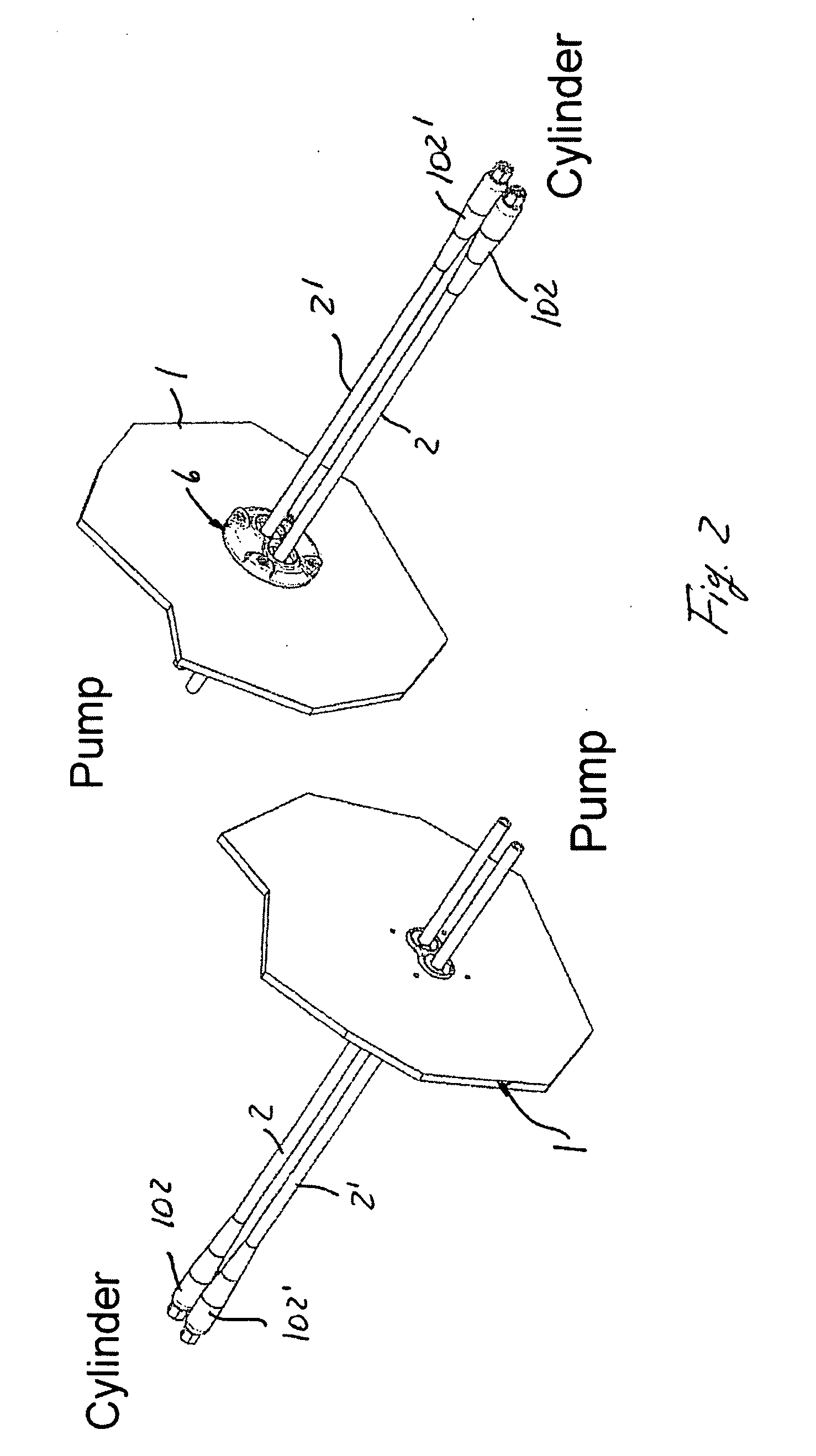
[0068]With reference to FIG. 1, wall 1 is a ship bulkhead and pipes 2, 2′ are pipes supplying the steering hydraulic circuit that connects the double-delivery pump, driven by the ship wheel, to the steering cylinder connected to the motor or motors. Bulkhead 1, for example, may be the wall by the motors that separates the stern board and the remaining part of the ship, but may also be any ship wall requiring to be sealingly traversed by pipes or cables. Moreover, while the following description relates to pipes 2, 2′, the present invention is equally applicable t...


PUM


Abstract

A guide element for passing one or more pipes, cables or the like through a wall includes an interposition element between the one or more pipes and the edge of the passage aperture, and an annular clamping flange on one or both sides of the wall. The flange is substantially concentric with the aperture and it is coupled to the wall along an annular perimetric strip surrounding the aperture. The interposition element is an elastic wedging and / or urging element between one or more pipes and the edge of the aperture, and the ring or flange clamps the interposition element in a wedged and / or urged condition.

Description

FIELD OF THE INVENTION[0001]The present invention relates to a guide element for the passage of one or more tubular elements such as pipes, cables or the like through a wall, more particularly, through a passage aperture made in the wall. The guide element includes an interposition element that is disposed between the tubular elements and the edge of the passage aperture and a fastening annular flange (or ring nut) that is disposed on one or both sides of the wall. The flange or ring nut is concentric in relation to the aperture and is fastened to the wall along an annular perimetric strip surrounding the aperture.BACKGROUND OF THE INVENTION[0002]Guide elements for the passage of pipes, cables or the like through walls are known. In the marine field such elements are used for passing, and possibly sealingly, ducts or cables through bulkheads, for example, pipes supplying oil within a circuit for controlling a steering cylinder.[0003]Ships steer by means of a pump driven by a wheel, ...

Claims


Application Information

Patent Timeline
IPC IPC(8): F16L5/00
CPCF16L5/02H02G3/22F16L5/14
Inventor GAI, GIORGIOMILANESE, ANDREA
Owner ULTRAFLEX
Learn More