Image processing method, image processing apparatus, and system

Active Publication Date: 2009-07-16
CANON KK
View PDF2 Cites 112 Cited by
  • Summary
  • Abstract
  • Description
  • Claims
  • Application Information

AI Technical Summary

Benefits of technology

[0027]The present invention has been made in consideration of the aforementioned problems, and has as its object to provide a technique for a

Problems solved by technology

When the optical systems are configured using low-cost lenses or the number of lenses which do not suffice to apply sufficient correction, the high image qualities of a captured image and that to be displayed cannot often be maintained due to aberrations of lenses.
That is, barrel- or pin-cushion-shaped images are often obtained due to distortion aberrations of lenses.
Also, red, blue, and green color bleedings appear at the boundaries of object images due to chromatic aberrations of magnification of lenses.
However, the aforementioned conventional techniques suffer the following problems.
However, in consideration of the calculation precision and the circuit scale of the interpolation calculations, a great reduction of the table size cannot be expected.
This also raises the threshold at the time of implementation in terms of both cost and implementation.
However, in an optical system configured by several lenses to correct vario

Method used


Image

  • Image processing method, image processing apparatus, and system
  • Image processing method, image processing apparatus, and system
  • Image processing method, image processing apparatus, and system

Examples


first embodiment

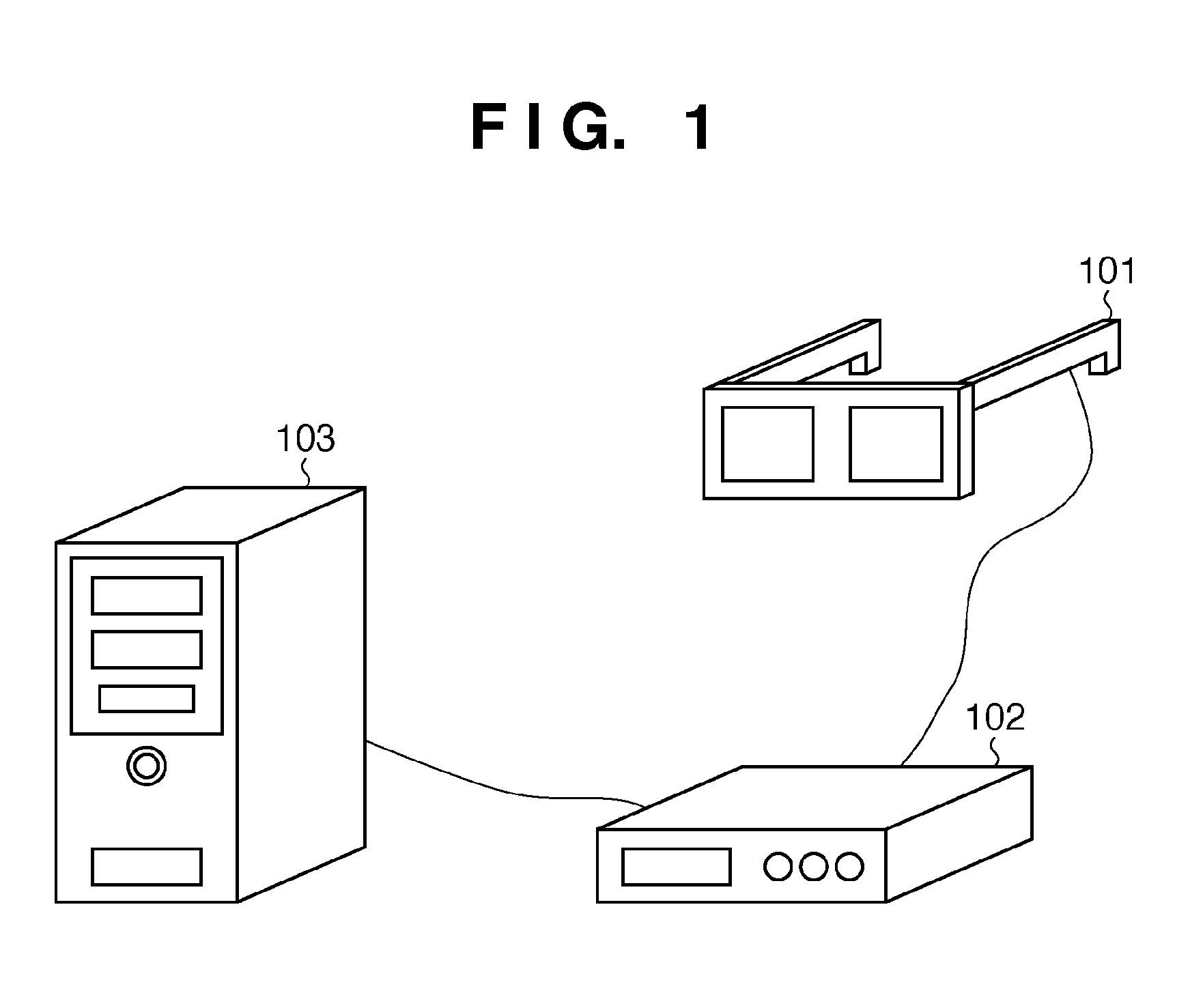
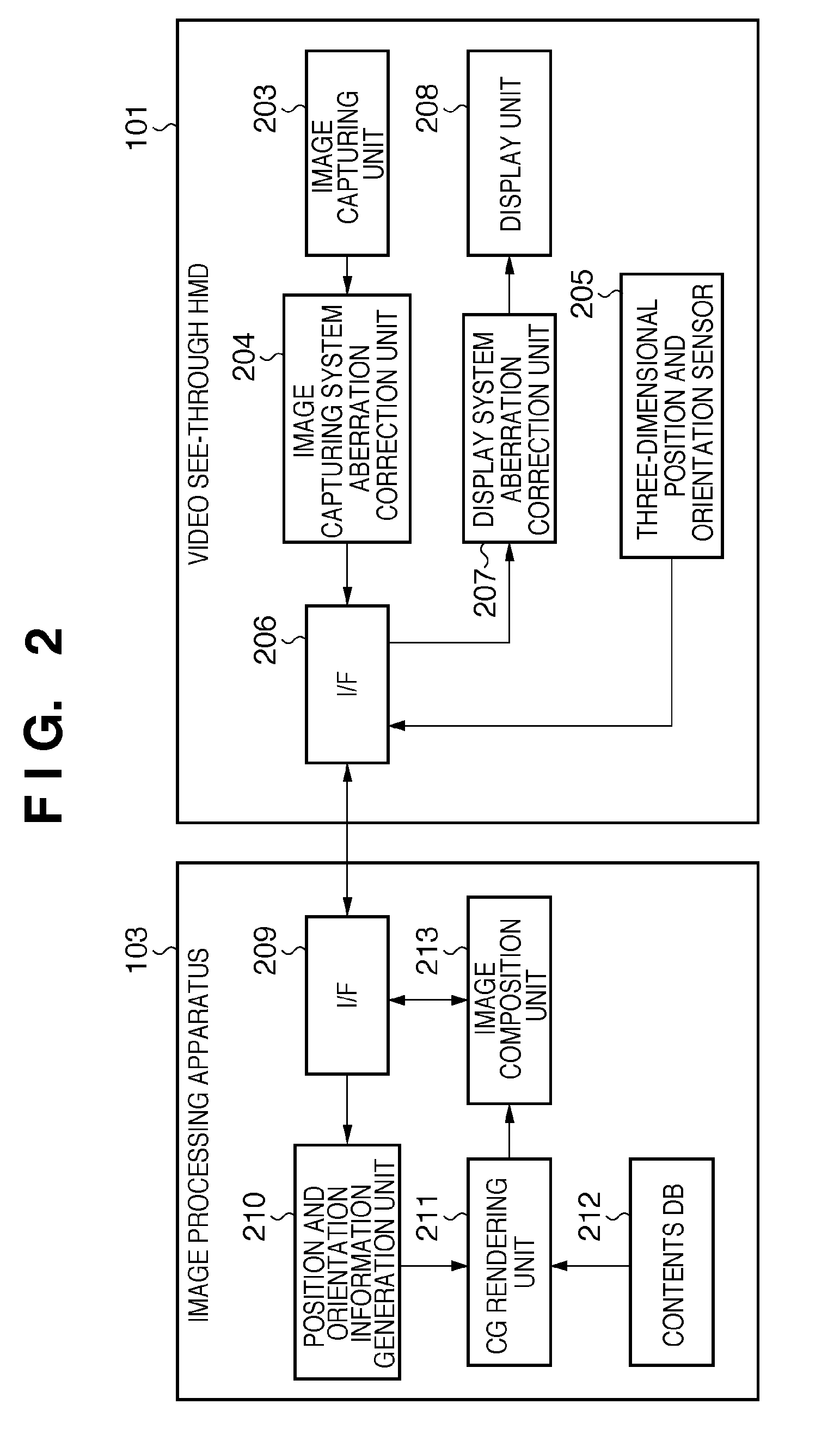
[0066]Mixed reality, that is, a so-called MR technique, as a technique for seamlessly blending physical and virtual worlds in real time, uses a display apparatus with an image capturing function (the display apparatus with the image capturing function will be abbreviated as an HMD hereinafter; however, a hand-held type apparatus such as binoculars may be used, and the present invention is not limited to a head-mounted apparatus). A CG image generated based on three-dimensional (3D) position and orientation information including the position, direction, and the like of the viewpoint of an HMD user is superimposed on an image (background image) of a physical space, which is captured by an image capturing unit of the HMD and is seen from the viewpoint of the HMD user, and that composite image is displayed on a display unit of the HMD. As a result, the HMD user can experience mixed reality as if an object (virtual object) rendered by CG were existing on the observed physical space.

[0067...

second embodiment

[0175]In the first embodiment, coordinate values of the X-Y, that is, two-dimensional coordinate system are stored as the table for color misregistration correction. In this embodiment, the distances between the coordinates after conversion of the reference color and those after conversion of the remaining colors are stored as a table. In this embodiment, the coordinate values of representative sampling points are stored in place of all the coordinates as reference pixels of the reference color and remaining colors, and coordinates between neighboring sampling points are calculated by interpolation calculations. Only differences between this embodiment and the first embodiment will be described below with focusing on these points.

[0176]FIG. 16 is a block diagram showing an example of the functional arrangement of the aberration correction LSI 408 according to this embodiment. In FIG. 16, a description of the same components as in FIG. 8 will not be repeated, and only different compo...

third embodiment

[0196]In the first and second embodiments, converted coordinates are calculated by table-lookup type address conversion. However, in this embodiment, the converted coordinates are calculated using an approximate polynomial to omit the reference table itself. Only differences between this embodiment and the first embodiment will be described below.

[0197]FIG. 20 is a block diagram showing an example of the functional arrangement as a modification of the color misregistration amount calculation unit 805. In FIG. 20, a description of the same components as in FIG. 8 will not be repeated, and only different components will be described.

[0198]Reference numeral 2001 denotes a color misregistration amount calculation unit.

[0199]Reference numeral 2002 denotes a table which stores parameters required for color misregistration amount calculations. In the first and second embodiments, coordinates after conversion corresponding to reference pixels are stored. However, in this embodiment, coeffic...


PUM


Abstract

One of a plurality of color components which form pixels in an image that is influenced by chromatic aberrations caused by an optical system is selected as a reference color, and coordinates after conversion are calculated by applying conversion for correcting a distortion of the optical system with respect to the image to coordinates of pixels in association with the reference color. Correction values indicating amounts of color misregistration are calculated using the proportional relationship of difference values between the calculated coordinates and coordinates obtained by applying the conversion to coordinates of the image in association with remaining colors except for the reference color of the plurality of color components. Based on the calculated correction values, coordinates obtained by applying the conversion to coordinates of the image in association with the remaining colors are calculated.

Description

BACKGROUND OF THE INVENTION[0001]1. Field of the Invention[0002]The present invention relates to a technique for correcting chromatic aberrations of an optical system and, more particularly, to a technique for correcting chromatic aberrations generated in an image capturing system or display system of an HMD (Head Mounted Display).[0003]2. Description of the Related Art[0004]In recent years, as a technique for seamlessly blending physical and virtual worlds in real time, mixed reality, that is, a so-called MR (Mixed Reality) technique is known. As one MR technique, the following technique is known. That is, using a video see-through HMD (Head Mounted Display; to be referred to as “HMD” hereinafter), an object which nearly matches an object observed from the pupil position of the user who wears the HMD (to be referred to as an HMD user hereinafter) is captured by a video camera or the like. By displaying an MR image obtained by superimposing a CG (Computer Graphics) image on that cap...

Claims


Application Information

Patent Timeline
IPC IPC(8): G09G5/00
CPCG02B27/0025G02B27/017G02B2027/011H04N9/045G02B2027/014G09G5/00G09G5/026G02B2027/0116H04N25/611
Inventor TSUJIMOTO, TAKUYAINOGUCHI, KAZUTAKA
Owner CANON KK
Why Eureka
Try Eureka