
Liquid ejection control device, method, and program

a control device and liquid ejection technology, applied in the direction of spacing mechanisms, printing mechanisms, printing, etc., can solve the problems of defective nozzles all over a plurality of areas, small chance, and trouble in forming raster lines, so as to prevent the ejection rate of liquid, prolong the fixing time, and prevent the effect of ejection

Inactive Publication Date: 2009-07-16
SEIKO EPSON CORP
View PDF6 Cites 1 Cited by
  • Summary
  • Abstract
  • Description
  • Claims
  • Application Information

AI Technical Summary

Benefits of technology

The invention provides a printer that can control the ejection of liquid from a nozzle that may cause problems. The printer uses a method to control the ejection rate of liquid in a way that reduces the negative impact of troublesome nozzles. This is accomplished by dispersing the nozzles in a way that ejects liquid in a way that reduces the negative impact of the troublesome nozzle. The printer can also have multiple groups of nozzles that eject liquid in a different direction to further reduce the negative impact of troublesome nozzles. The control of the ejection rate can be based on the characteristics of the liquid and the ejection object medium. This allows for proper control of the ejection rate for different liquids. Overall, the invention provides a printer that can control the ejection of liquid from nozzles that may cause problems and improve the overall performance of the printer.

Problems solved by technology

For this instance, in the case in which some ejection nozzles have a trouble with liquid ejection with respect to the raster line, such a trouble influences formation of the raster line.
The overlap-type liquid ejection method is advantageous in that it is possible to reduce the influence attributable to the trouble of an ejection nozzle in comparison with a non-overlap-type liquid ejection performed using a single ejection nozzle which is troublesome but is disadvantageous in that it enhances on the contrary influence attributable to the trouble of the ejection nozzle in the case in which ejection amount of the troublesome ejection nozzle is larger than that of normal ejection nozzles.
In the case in which the ejection nozzle having a maximum the ejection rate is troublesome, such a trouble negatively influences the overall ejection result even in an overlap-type print.
That is, there is a little chance that the defective nozzles exist all over a plurality of areas in the subordinate scan direction.
In addition, since the low ejection rate nozzle group which is shut in by the ejection nozzle groups which have the maximum and uniform ejection rate includes the ejection nozzle having the poor stability in the ejection characteristic, the ejection characteristics of all of the ejection nozzles need to be obtained beforehand.

Method used


Image

  • Liquid ejection control device, method, and program
  • Liquid ejection control device, method, and program
  • Liquid ejection control device, method, and program

Examples


Embodiment Construction

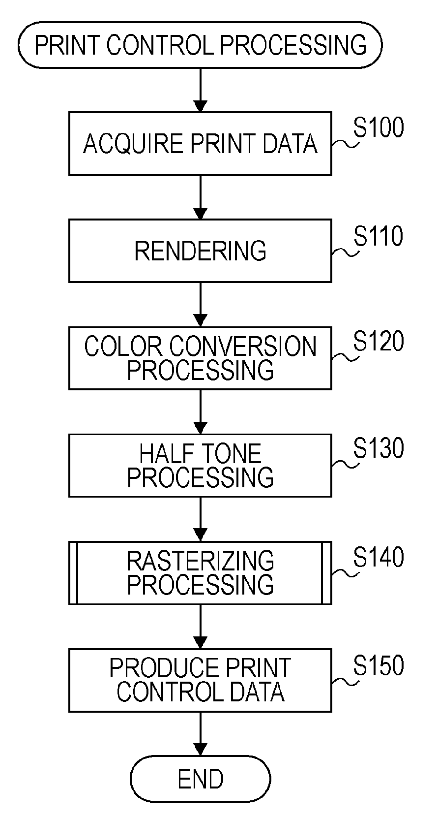
[0031]Embodiments of the invention will be described in the following order:[0032]A. Structure of device[0033]B. Print control processing[0034]C. Print result[0035]D. Combination of a plurality of inks[0036]E. Modification

A. Structure of Device

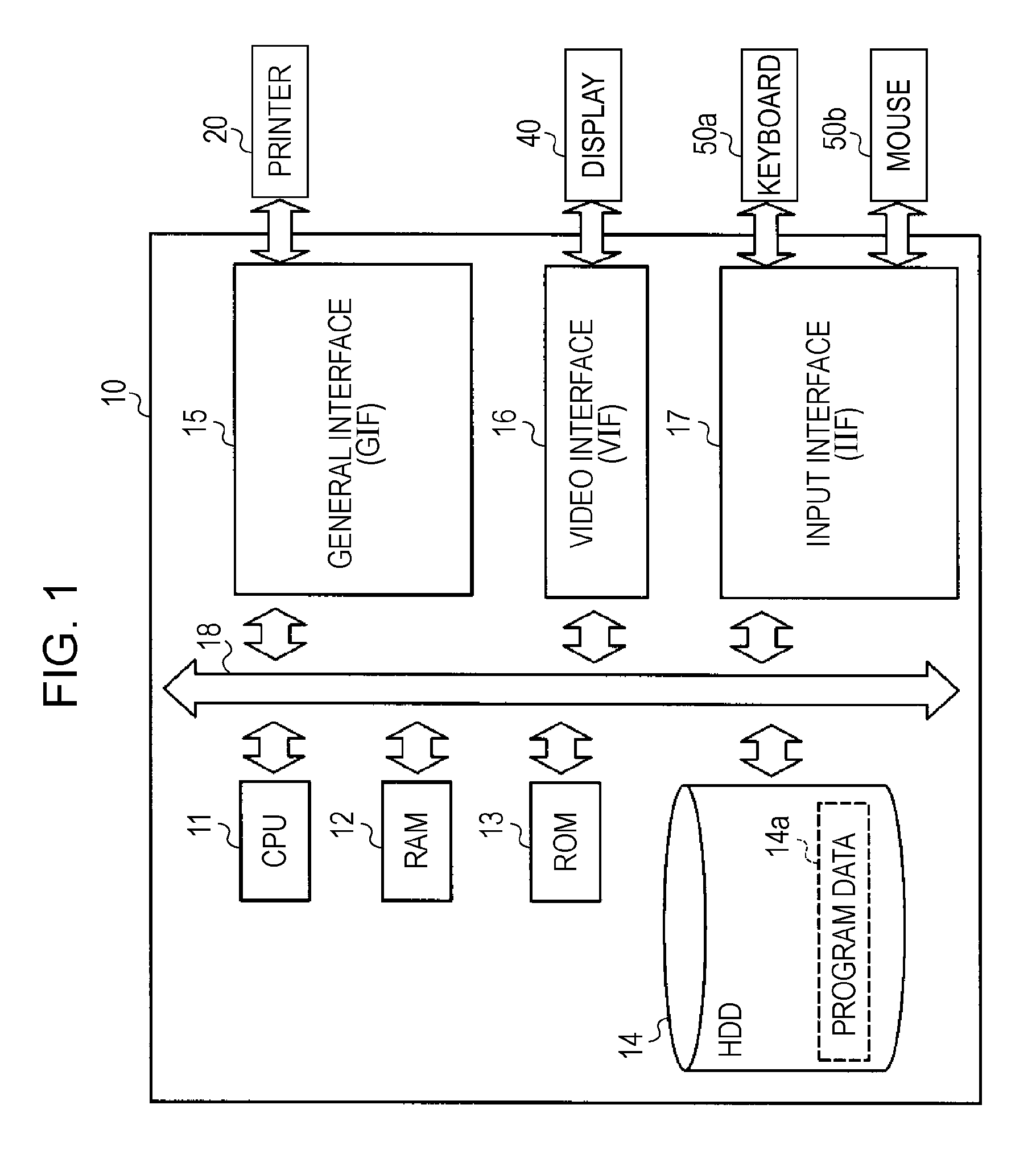
[0037]FIG. 1 schematically shows hardware configuration of a liquid ejection control device according to one embodiment of the invention. In FIG. 1, the liquid ejection control device is primarily constituted as a computer 10. The computer 10 includes a CPU 11, a RAM 12, a ROM 13, a hard disk drive (HDD) 14, a general interface (GIF) 15, a video interface (VIF) 16, an input interface (IIF) 17, and a bus 18. The bus 18 enables data communication to be performed between respective members 11 to 17 which constitute the computer 10, and communication is controlled by a chip set (not shown). The HDD 14 stores program data 14a for executing various programs including an operating system (OS). The program data 14a is developed in the RAM 12 and the C...


PUM


Abstract

A liquid ejection control device, which makes an ejection object medium and an ejection nozzle column which ejects liquid relatively scan in a primary scan direction which almost perpendicularly intersects the nozzle ejection column and makes the ejection object medium and the ejection nozzle column relatively scan in a subordinate scan direction which almost perpendicularly intersects the primary scan direction. The liquid ejection control device includes an ejection control unit controlling ejections of ejection nozzles such that ejection rates of the ejection nozzles vary according to positions of the ejection nozzles in the subordinate scan direction, the variation being set such that the ejection nozzles having a maximum ejection rate are dispersed in the subordinate scan direction, when a rate of an ejection, which is charged by a predetermined ejection nozzle, to a primary scan line at the same position in the subordinate scan direction is called an ejection rate.

Description

BACKGROUND[0001]1. Technical Field[0002]The present invention relates to a liquid ejection control device, method, and program which makes an ejection object medium and an ejection nozzle column, which ejects liquid, relatively primarily scan in a primary scan direction which almost perpendicularly intersects the ejection nozzle column, and makes the ejection object medium and the ejection nozzle column relatively subordinately scan in a subordinate scan direction which almost perpendicularly intersects the primary scan direction.[0003]2. Related Art[0004]JP-A-2002-11859 discloses an overlap-type liquid ejection method in which a raster line is formed by performing a plural number of times of primary scan operations with respect to a raster line on the ejection object medium. With such an overlap-type liquid ejection method, it is possible to suppress influence attributable to variance of primary scan operations, and therefore it is possible to obtain the print result with good imag...

Claims


Application Information

Patent Timeline
Patent Type & Authority Applications(United States)
IPC IPC(8): B41J2/205
CPCB41J19/142
Inventor OTOKITA, KENJI
Owner SEIKO EPSON CORP
Learn More