Qkd stations with fast optical switches and qkd systems using same

Inactive Publication Date: 2009-07-16
MAGIQ TECH INC
View PDF14 Cites 41 Cited by
  • Summary
  • Abstract
  • Description
  • Claims
  • Application Information

AI Technical Summary

Problems solved by technology

As a consequence, an eavesdropper (“Eve”) that attempts to intercept or otherwise measure the exchanged qubits will introduce errors that

Method used


Image

  • Qkd stations with fast optical switches and qkd systems using same
  • Qkd stations with fast optical switches and qkd systems using same
  • Qkd stations with fast optical switches and qkd systems using same

Examples


first example embodiment

I. First Example Embodiment

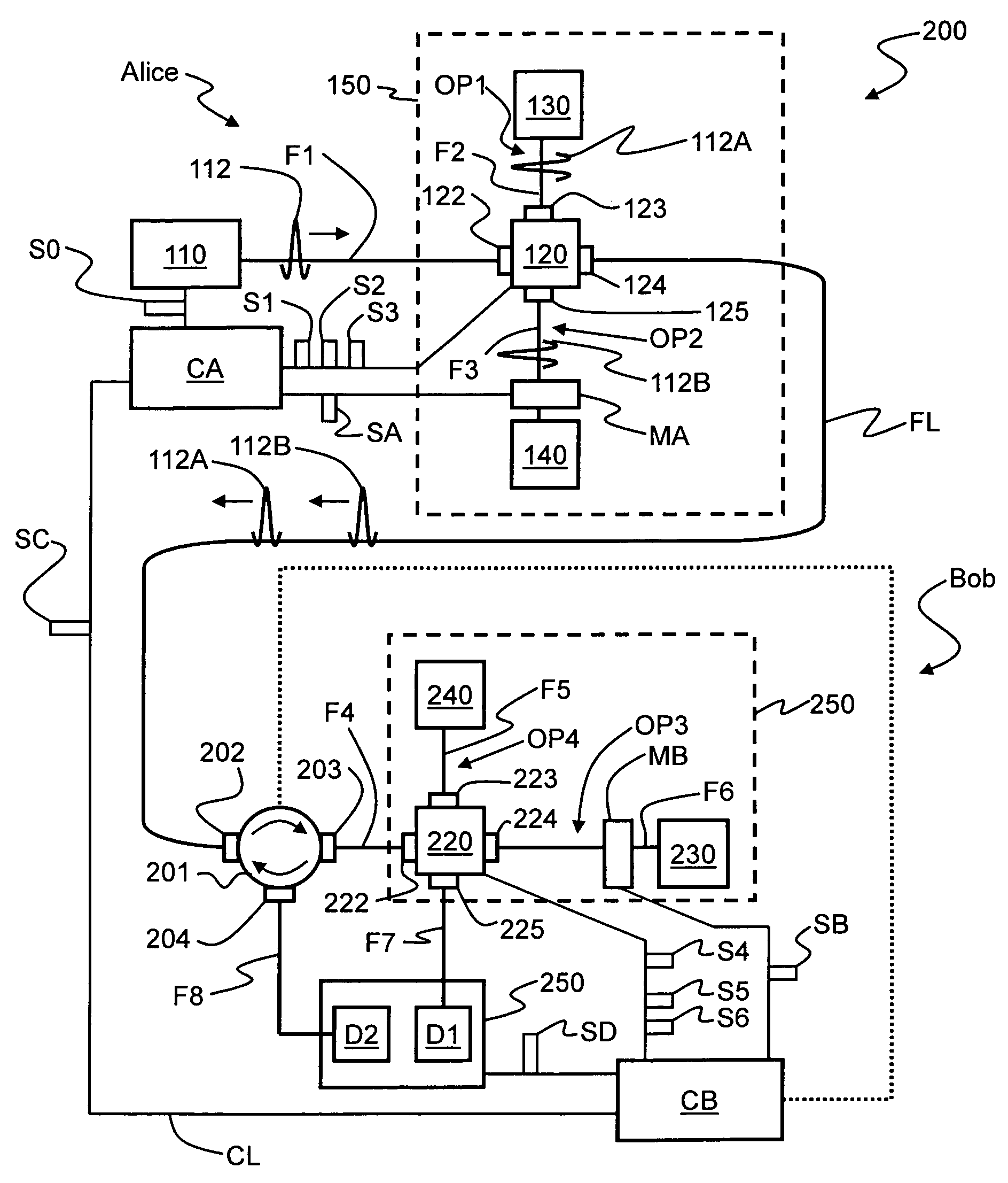
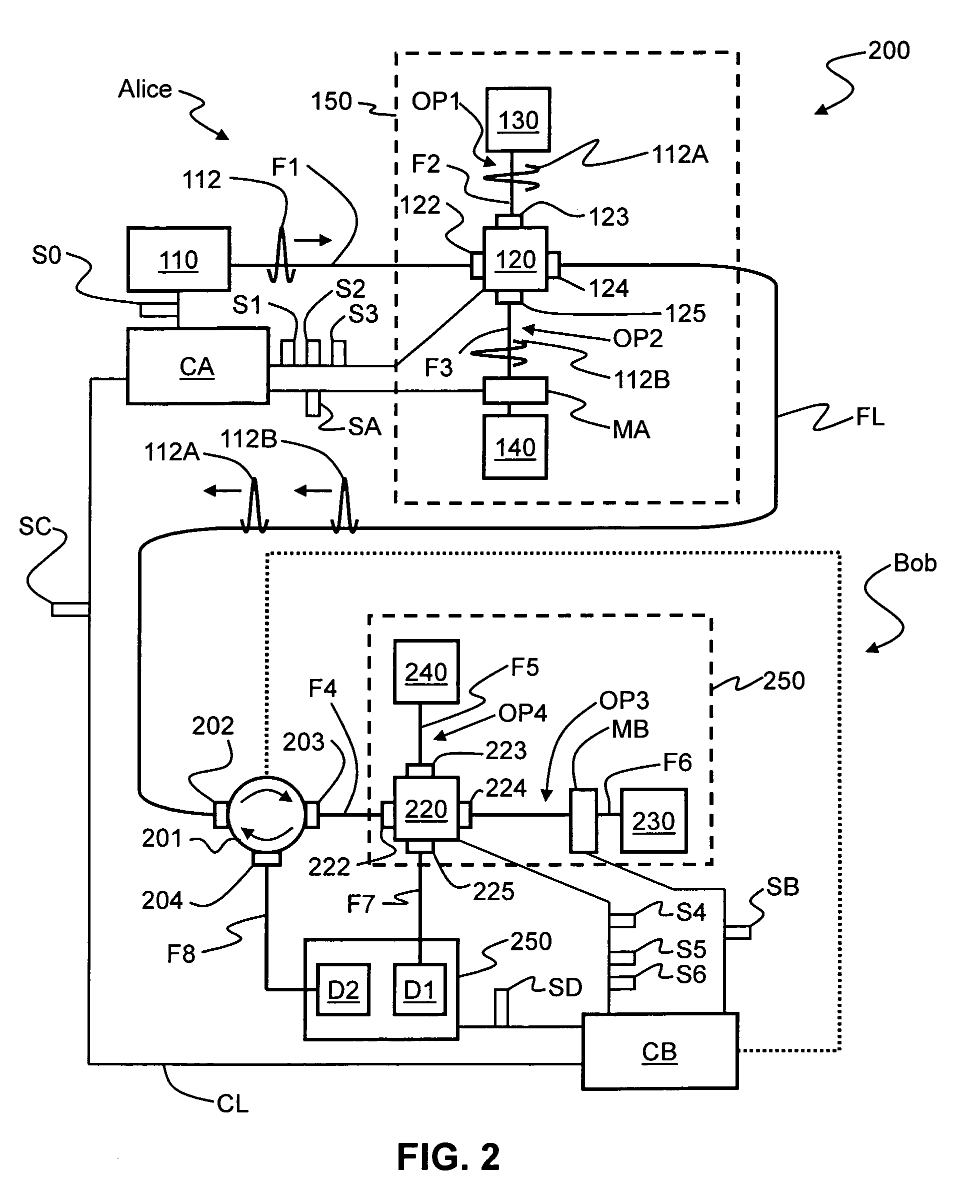
[0024]FIG. 2 is a schematic diagram of an example embodiment of a QKD system 200 according to the present invention that utilizes QKD stations having fast optical switches and that obviates the need for beamsplitters and optical fiber interferometer loops. QKD system 200 includes two QKD stations Alice and Bob. Alice and Bob are optically coupled, e.g., by an optical fiber link FL. The two QKD stations Alice and Bob are described below, followed by the method of operation of QKD system 100.

Alice

[0025]Alice includes a light source 110 adapted to emit single-photon-level optical pulses 112. In an example embodiment, optical pulses 112 are “quantum signals” that are either each made up of single photons, or are weak coherent pulses (WCPs) having, for example, less than a single photon on average as calculated based on Poissonian statistics.

[0026]Light source 110 is optically coupled to a fast optical switch 120. In an example embodiment, a first optical fiber...

second example embodiment

II. Second Example Embodiment

[0052]FIG. 3 is a schematic diagram of an example embodiment of a QKD system 300 according to the present invention. QKD system 300 is similar to the prior art QKD system 10 shown in FIG. 1. In QKD system 300, however, light source L1 is a weak coherent pulse (WCP) source and fast optical switches 310 and 320 replace beamsplitters 13 and 21. Alice also has a controller CA and Bob has a controller CB. Controllers CA and CB are operably coupled via a communication link CL that carries synchronization signals SC in the manner described in connection with QKD system 200 of FIG. 2.

[0053]Fast optical switch 310 has an output port 312, and two side ports 313 and 314. Similarly, fast optical switch 320 has an input port 322, and two side ports 323 and 324. Fast optical switch 310 has first and second operating states. In the first operating state, the switch directs light entering at side port 313 out of output port 312. In the second operating state, the switch...

third example embodiment

III. Third Example Embodiment

[0058]FIG. 4 is a schematic diagram of a QKD system 400 similar to that of QKD system 300 of FIG. 3, but wherein the light source 110 is a single photon source, and wherein the system includes a single fast optical switch 320 at Bob.

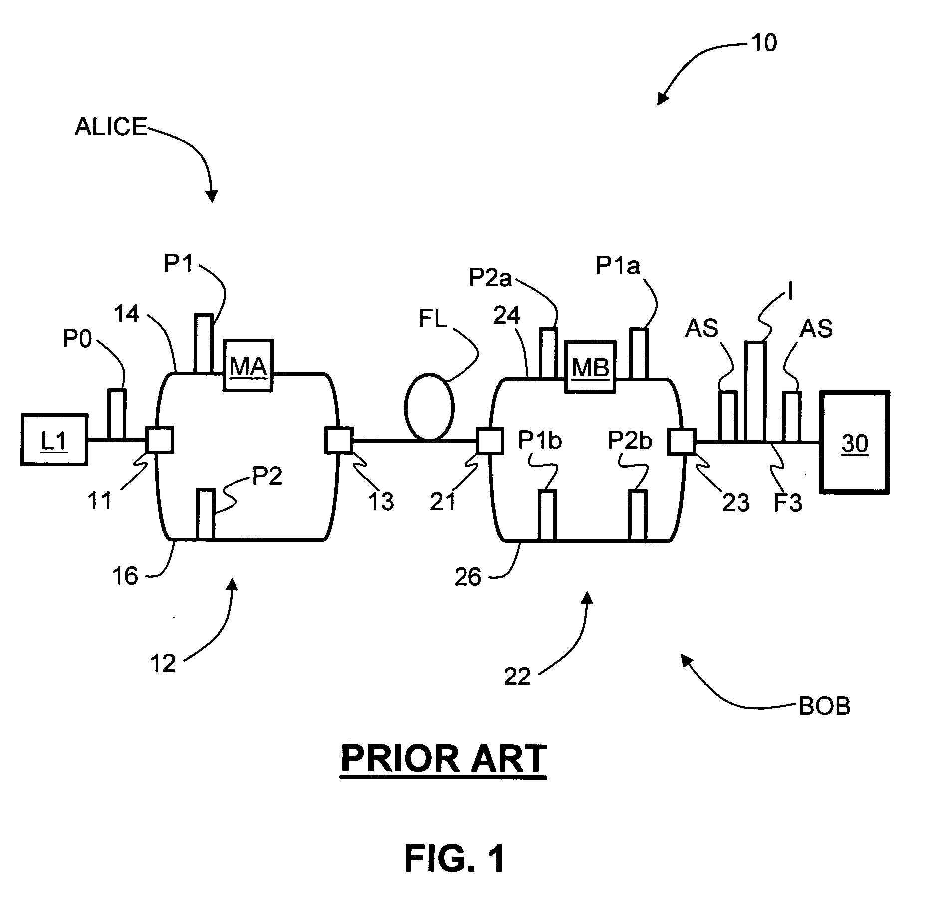
[0059]In the operation of QKD 400, Alice's controller CA sends light source 110 an activation signal S0 that causes the light source SPS to generate a single-photon quantum signal P0. At the same time, controller CA generates synchronization signal SC, which travels over to Bob's controller CB over communication link CL. Single-photon quantum signal P0 travels to beamsplitter 11. Because quantum signal P0 is a single photon, instead of this pulse being split into two, the pulse is described in terms of the probability of it being in one arm of the loop or the other. Hence, pulse P0 is shown as being in both optical fiber sections 14 and 16. Controller CA activates phase modulator MA to coincide with the expected arrival time ...


PUM


Abstract

The quantum key distribution (QKD) systems (200, 300, 400) of the invention includes first and second QKD stations (Alice and Bob) according to the present invention, wherein either one or both QKD stations include fast optical switches (120, 220, 310, 320). Each fast optical switch is respectively optically coupled to two different round-trip optical paths (OP1 and OP2 at Alice, OP3 and OP4 at Bob) of different length that define respective optical path differences OPDA and OPDB, wherein OPDA=OPDB. By switching the fast optical switches using timed switching signals (S1-S3 at Alice, S4-S6 at Bob) from their corresponding controllers (CA at Alice, CB at Bob), the quantum signals—which can be single-photon or weak-coherent pulses—can be generated from a single optical pulse (112), randomly selectively encoded while traversing the optical paths in Alice and Bob, and then interfered and measured (detected) at Bob. The QKD system has less loss as compared to conventional fiber-based QKD systems because it omits at least some of the beamsplitters in conventional QKD systems.

Description

TECHNICAL FIELD OF THE INVENTION[0001]The present invention relates to quantum cryptography, and in particular relates to quantum key distribution (QKD) systems and QKD stations used in QKD systems.BACKGROUND ART[0002]QKD involves establishing a key between a sender (“Alice”) and a receiver (“Bob”) by using either single-photons or weak (e.g., 0.1 photon on average) optical signals (pulses) called “qubits” or “quantum signals” transmitted over a “quantum channel.” Unlike classical cryptography whose security depends on computational impracticality, the security of quantum cryptography is based on the quantum mechanical principle that any measurement of a quantum system in an unknown state will modify its state. As a consequence, an eavesdropper (“Eve”) that attempts to intercept or otherwise measure the exchanged qubits will introduce errors that reveal her presence.[0003]The general principles of quantum cryptography were first set forth by Bennett and Brassard in their article “Qu...

Claims


Application Information

Patent Timeline
IPC IPC(8): H04L9/00H04L9/08
CPCH04L9/0858H04B10/70
Inventor TRIFONOV, ALEXEI
Owner MAGIQ TECH INC
Why Eureka
Try Eureka