

Camera system and camera body
a camera system and camera body technology, applied in the field of camera systems, can solve the problems of inability to communicate properly between an interchangeable lens and a camera main body made by different manufacturers, and the operation of image blur correction cannot be properly performed, so as to achieve the effect of less deterioration of optical performan
- Summary
- Abstract
- Description
- Claims
- Application Information
AI Technical Summary
Benefits of technology
Problems solved by technology
Method used
Image

Examples
first embodiment
1: Overall Configuration of Camera System
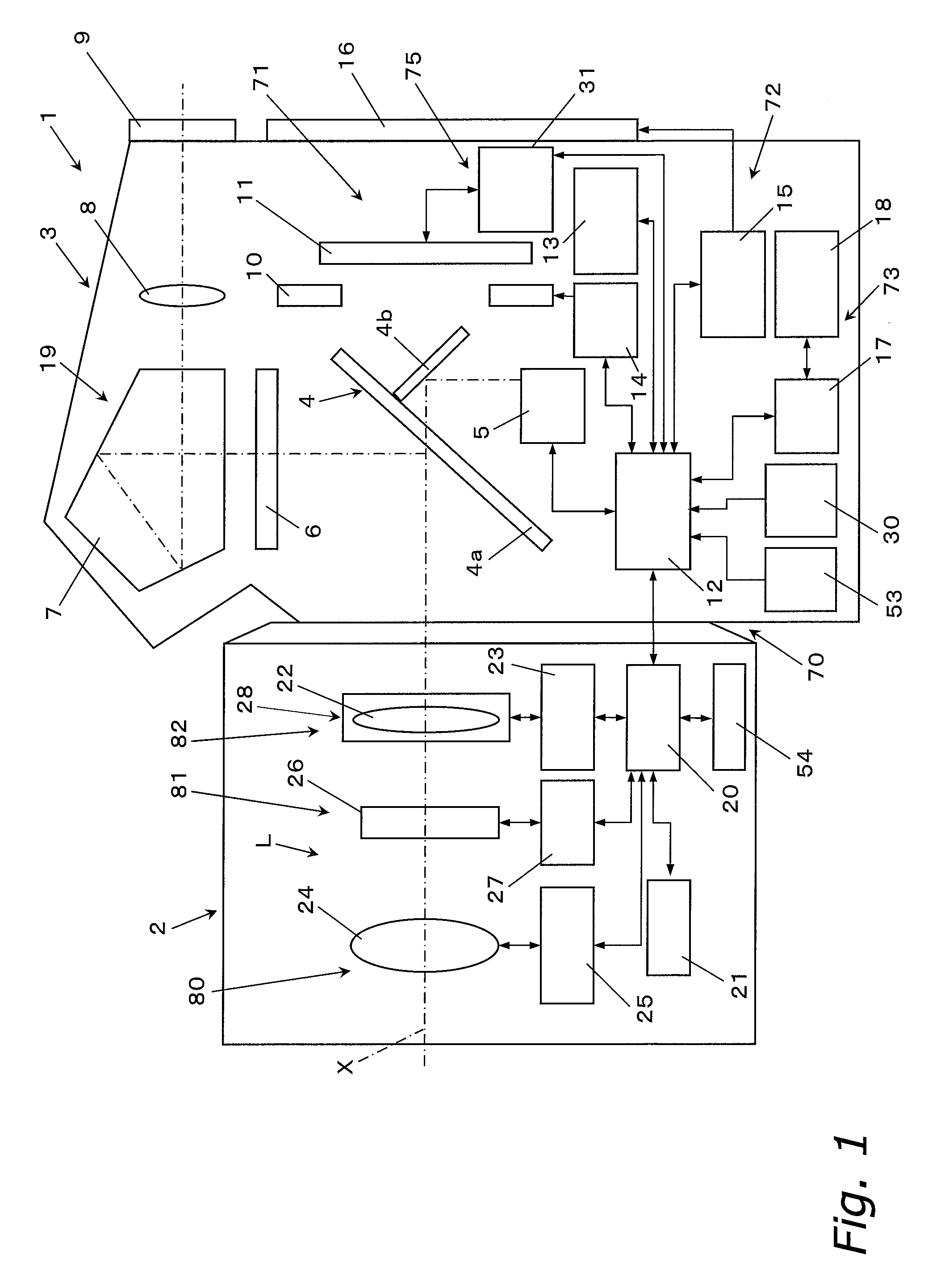
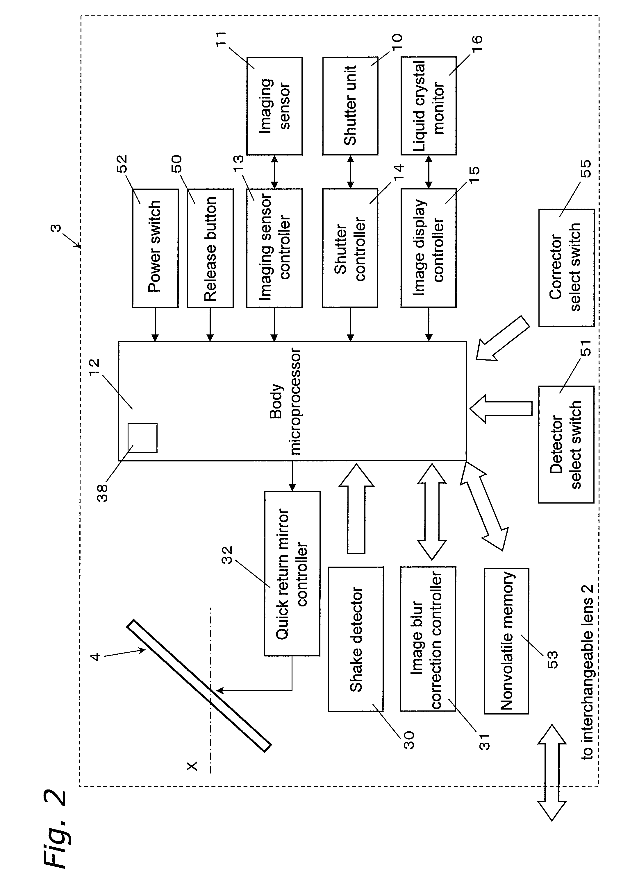
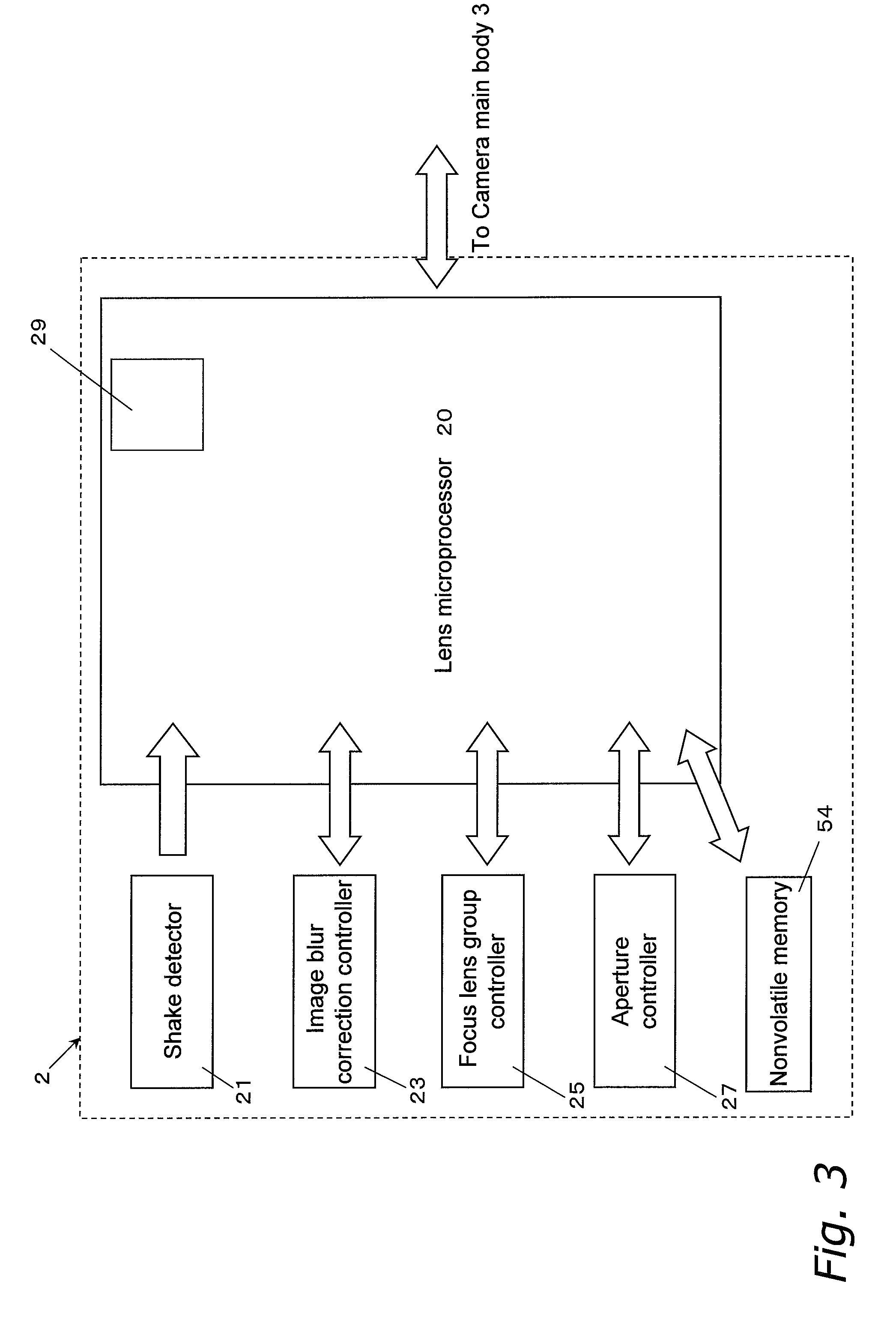
[0120]The camera system according to the first embodiment of the present invention will be described through reference to FIGS. 1 to 3. FIG. 1 is a diagram of the overall configuration of the camera system according to the first embodiment of the present invention, FIG. 2 is a simplified diagram of the configuration of the camera main body, and FIG. 3 is a simplified diagram of the configuration of the interchangeable lens.
[0121]As shown in FIG. 1, a camera system 1 is an interchangeable lens type of single-reflex digital camera system, and mainly includes a camera main body 3 having the primary function of the camera system 1, and an interchangeable lens 2 that is removably attached to the camera main body 3. The interchangeable lens 2 is mounted on a lens mount 70 provided to the front face of the camera main body 3.
[0122]1.1: Camera Main Body
[0123]The camera main body 3 mainly includes an imaging unit 71 for forming an image of a subject, ...
second embodiment
[0168]In the above embodiment, the image blur correction device was automatically selected by the body microcomputer 12 when the interchangeable lens 2 was mounted. A case in which the selection is made manually by the user is also possible, however. A camera system according to a second embodiment of the present invention will be described through reference to FIGS. 8 and 9. FIGS. 8 and 9 are flowcharts of the selecting operation of the image blur correction device according to a third embodiment of the present invention. Those components that are the same as in the above embodiment will be numbered the same, and will not be described again.
[0169]As shown in FIG. 2, the camera main body 3 includes a detector select switch 51 and a corrector select switch 55. The detector select switch 51 is a switch that allows either the main body shake detector 30 or the lens shake detector 21 to be selected from the outside, and the corrector select switch 55 is a switch that allows either the m...
third embodiment
[0180]With the first embodiment above, when an image blur correction device is installed in the camera main body 3 and the interchangeable lens 2, it is predetermined which shake detector will be given preference and which image blur corrector will be given preference. Also, with the second embodiment above, the user selects one shake detector and one image blur corrector.
[0181]However, it is also possible to determine which shake detector and which image blur corrector will be selected on the basis of specific information held in the nonvolatile memories 53 and 54 or the memory components 29 and 36. The camera system according to a third embodiment of the present invention will be described through reference to FIGS. 10 and 11. FIGS. 10 and 11 are flowcharts of the selecting operation of the image blur correction device according to the third embodiment of the present invention. Those components that are the same as in the above embodiment will be numbered the same, and will not be...
PUM
 Abstract
Description
Claims
Application Information