Digital signal conversion method and digital signal conversion device

a digital signal and conversion method technology, applied in the field of digital signal conversion methods and digital signal conversion devices, can solve the problems of deterioration of signals and inability to efficiently carry out resolution conversion of video signals as described above, and achieve the effect of less deterioration of signals and efficient conversion processing

Inactive Publication Date: 2005-11-08
SONY CORP
View PDF8 Cites 19 Cited by
  • Summary
  • Abstract
  • Description
  • Claims
  • Application Information

AI Technical Summary

Benefits of technology

[0024]In view of the foregoing status of the art, it is an object of the present invention to provide a digital signal conversion method and a digital signal conversion device which enable efficient conversion processing such as resolution conversion with less deterioration in signals by reducing the quantity of arithmetic processing of the data quantity of signals which are processed by resolution conversion for conversion to a different format.

Problems solved by technology

Therefore, there arises a problem that resolution conversion of video signals as described above cannot be carried out efficiently.
Also, since errors are accumulated by increase in the quantity of calculation, there arises a problem of deterioration in signals.

Method used


Image

  • Digital signal conversion method and digital signal conversion device
  • Digital signal conversion method and digital signal conversion device
  • Digital signal conversion method and digital signal conversion device

Examples


first embodiment

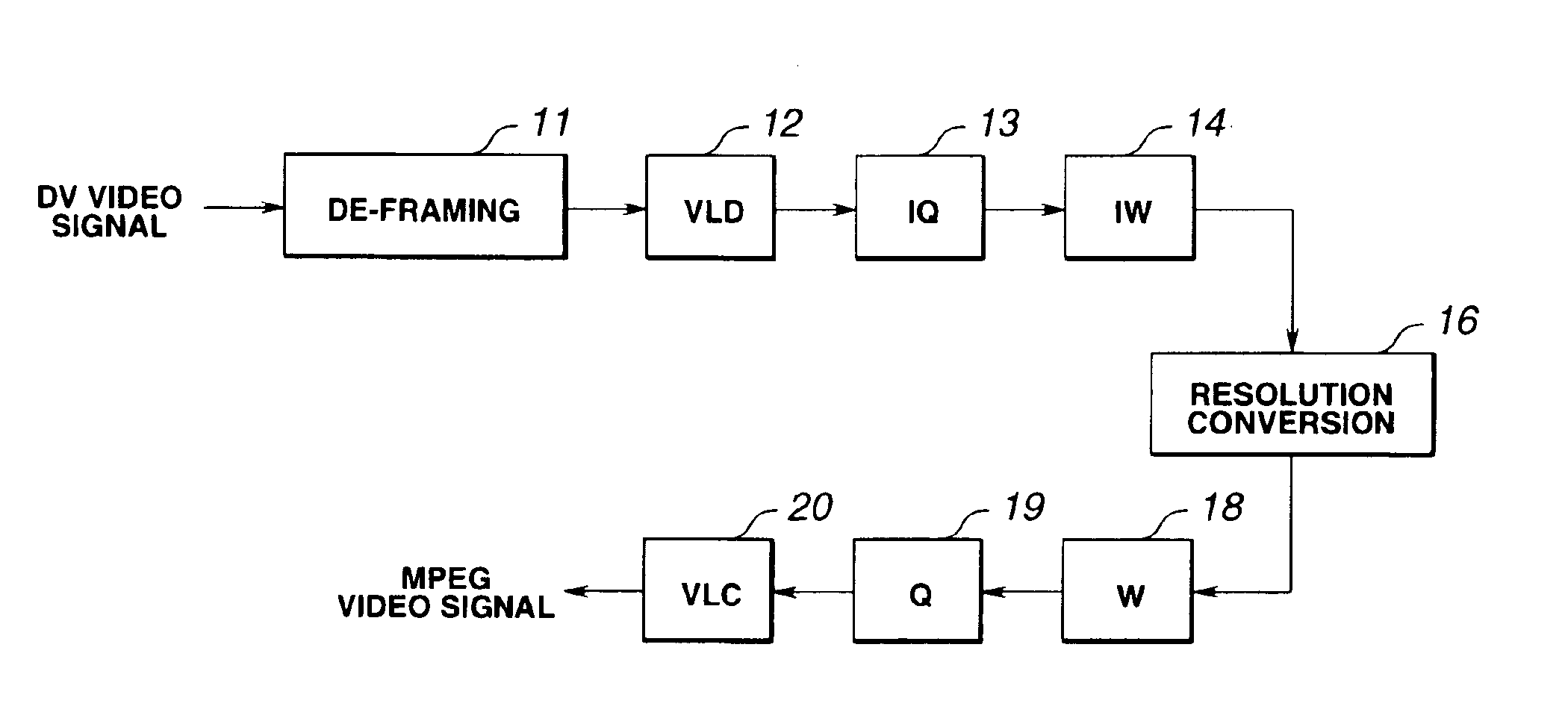
[0069]FIG. 1 shows an exemplary structure of essential portions of a digital signal conversion device as the present invention. Although signal conversion is exemplified by resolution conversion, it is a matter of course that signal conversion is not limited to resolution conversion and that various types of signal processing such as format conversion and filter processing can be employed.

[0070]In this digital signal conversion device, a video signal (hereinafter referred to as DV video signal) of the above-described so-called “DV format” is inputted as a first digital signal, and a video signal (hereinafter referred to as MPEG video signal) of a format in conformity to the MPEG (Moving Picture Experts Group) standard is outputted as a second digital signal.

[0071]A de-framing section II is adapted for cancelling framing of the DV video signal. In this de-framing section 11, the DV video signal framed in accordance with the predetermined format (so-called DV format) is restored to a ...

second embodiment

[0137]The above-described resolution conversion is for contracting an image. Hereinafter, resolution conversion processing for enlarging an image will be described as a

[0138]FIGS. 9A to 9C schematically show the state where a DV video signal is converted to an MPEG2 video signal by the digital signal conversion method according to the present invention.

[0139]Also in the following description, one-dimensional DCT coefficients are used. However, similar processing can be carried out on two-dimensional DCT coefficients.

[0140]First, 8-point inverse discrete cosine transform (8-point IDCT) is carried out on a block (u) consisting of eight orthogonal coefficients (DCT coefficients g0 to g7) shown in FIG. 9A, thus restoring eight pixel data (h0 to h7).

[0141]Next, the block consisting of eight pixel data is divided into two parts, thus generating two partial blocks each consisting of four pixel data.

[0142]Then, 4-point DCT is carried out on the two partial blocks each consisting of four DCT...

third embodiment

[0154]In the digital signal conversion device of the third embodiment shown in FIG. 11, the weighting processing section 21 is provided on the subsequent stage to the resolution converting section 16. However, the weighting processing section may be provided on the stage preceding the resolution converting section 16.


PUM


Abstract

An input digital signal of a first format (DV video signal) is restored to a variable-length code by having its framing cancelled by a de-framing section 11, then decoded by a variable-length decoding (VLD) section 12, inversely quantized by an inverse quantizing (IQ) section 13, and inversely weighted by an inverse weighting (IW) section 14. Then required resolution conversion in the orthogonal transform domain (frequency domain) is carried out on the inversely weighted video signal by a resolution converting section 16. After that, the video signal having the resolution converted is weighted by a weighting (W) section 18, then quantized by a quantizing (Q) section 19, coded by a variable-length coding by a variable-length coding (VLC) section 20, and outputted as a digital signal of a second format (MPEG video signal).

Description

TECHNICAL FIELD[0001]This invention relates to conversion processing of digital signals compression-coded by using orthogonal transform such as discrete cosine transform (DCT), and particularly to a digital signal conversion method and a digital signal conversion device for converting the resolution between compressed video signals of different formats.BACKGROUND ART[0002]Conventionally, discrete cosine transform (DCT), which is a kind of orthogonal transform coding, has been used as a coding system for efficiently compression-coding still picture data and dynamic picture data. In handling such digital signals on which orthogonal transform has been carried out, it is sometimes necessary to change the resolution or transform base.[0003]For example, in the case where a first orthogonally transformed digital signal having a resolution of 720×480 pixels as an example of home digital video format is to be converted to a second orthogonally transformed-digital signal having a resolution o...

Claims


Application Information

Patent Timeline
Patent Type & Authority Patents(United States)
IPC IPC(8): H04N7/26H04N7/50H04N7/46H04N7/30H04N19/103H04N19/114H04N19/126H04N19/134H04N19/136H04N19/137H04N19/146H04N19/176H04N19/186H04N19/196H04N19/40H04N19/423H04N19/503H04N19/51H04N19/513H04N19/577H04N19/59H04N19/60H04N19/61H04N19/625H04N19/85H04N19/88H04N19/91
CPCH04N19/56H04N19/197H04N19/176H04N19/46H04N19/196H04N19/122H04N19/61H04N19/60H04N19/107H04N19/126H04N19/137H04N19/186H04N19/152H04N19/48H04N19/547H04N19/57H04N19/40H04N19/59H04N19/13H04N19/124H04N19/91H04N11/04
Inventor YANAGIHARA, NAOFUMIIZUMI, NOBUAKI
Owner SONY CORP
Why Eureka
Try Eureka