Electrode and power storage device

a power storage device and electromechanical technology, applied in the direction of secondary cell servicing/maintenance, cell components, batteries, etc., can solve the problems of reducing the capacity of the power storage device, and achieve the effect of less deterioration, less deterioration and high capacity

Pending Publication Date: 2018-03-15
SEMICON ENERGY LAB CO LTD
View PDF4 Cites 17 Cited by
  • Summary
  • Abstract
  • Description
  • Claims
  • Application Information

AI Technical Summary

Benefits of technology

[0007]Another object of one embodiment of the present invention is to provide an electrode with less deterioration. Another object of one embodiment of the present invention is to provide an electrode with a high capacity. Another object of one embodiment of the present invention is to provide a long-life power storage device. Another object of one embodiment of the present invention is to provide a power storage device with less deterioration. Another object of one embodiment of the present invention is to provide a power storage device with high energy density. Another object of one embodiment of the present invention is to provide a highly reliable power storage device.
[0015]One embodiment of the present invention can provide a novel electrode. Another embodiment of the present invention can provide a novel power storage device.
[0016]Another embodiment of the present invention can provide an electrode with less deterioration. Another embodiment of the present invention can provide an electrode with a high capacity. Another embodiment of the present invention can provide a long-life power storage device. Another embodiment of the present invention can provide a power storage device with less deterioration. Another embodiment of the present invention can provide a power storage device with high energy density. Another embodiment of the present invention can provide a highly reliable power storage device.

Problems solved by technology

This elution might result in a reduction in the capacity of a power storage device.

Method used


Image

  • Electrode and power storage device
  • Electrode and power storage device
  • Electrode and power storage device

Examples


embodiment 1

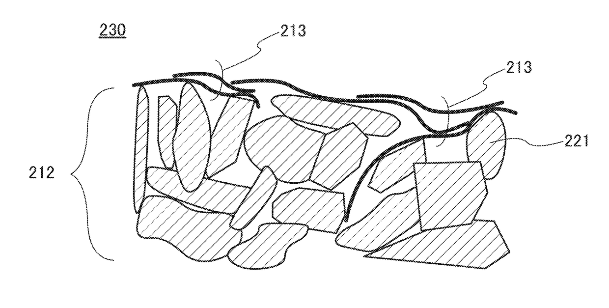
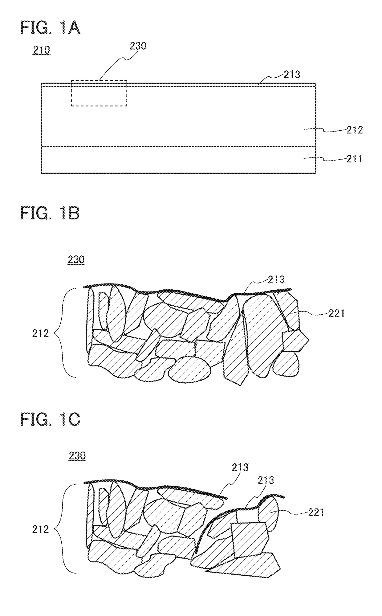
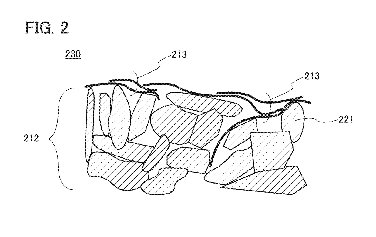
[0054]A power storage device of one embodiment of the present invention includes a layer containing a graphene compound, a positive electrode, and a negative electrode. The positive electrode and the negative electrode each contain an active material. When the power storage device includes the layer containing a graphene compound, for example, a metal released from the active material can be trapped in the layer. The layer is preferably provided in the vicinity of the active material so as to be, for example, partly in contact with the active material.

Structure Example

[0055]FIG. 1A illustrates an example of a cross section of an electrode of one embodiment of the present invention. An electrode 210 includes an active material layer 212 and a layer 213 over the active material layer 212.

[0056]The active material layer 212 contains an active material 221. The active material 221 contains an element M. The element M is preferably one or more elements selected from manganese, nickel, co...

embodiment 2

[0130]In this embodiment, a graphene compound of one embodiment of the present invention is described.

[0131]First, graphene and a graphene compound are described.

[0132]Graphene is a one-atom-thick sheet of carbon atoms having sp2 hybrid orbitals which are bonded to each other and arranged to have a hexagonal lattice structure on a plane. Bonds between carbon atoms in graphene are stronger than those in diamond; thus, graphene has extremely high resistance to deformation and pulling. However, graphene has extremely high electron conductivity and is not sufficiently permeable to lithium ions.

[0133]Graphene containing carbon atoms arranged in one atomic layer is referred to as single-layer graphene in some cases. Graphene including two or more and one hundred or less layers is referred to as multilayer graphene in some cases. The length in the longitudinal direction or the length of the major axis in a plane in each of single-layer graphene and multilayer graphene is greater than or eq...

specific example

[0177]Next, examples of a silicon compound that has a chain group having one or more ester groups or carboxyl groups are shown below. With the use of any of such silicon compounds, a graphene compound chemically modified with a chain group having one or more ester groups or carboxyl groups can be formed. Compounds 100 to 149 and compounds 156 to 161, which have ester groups, are classified into esters. Compounds 150 to 155, which have carboxyl groups, are classified into carboxylic acids.

[0178]With the use of any of the above silicon compounds, the graphene compound that has a chain group having one or more ester groups or carboxyl groups can be formed. Note that the graphene compound of one embodiment of the present invention may be formed without using any of the above-mentioned silicon compounds.

[0179]Next, examples of the silylating agent that has a chain group having two or more ether bonds are shown below. With the use of any of such silylating agents, a graphene compound chem...


PUM

PropertyMeasurementUnit
charge rateaaaaaaaaaa
lengthaaaaaaaaaa

Abstract

A novel electrode, a novel power storage device, an electrode with less deterioration, an electrode with a high capacity, a long-life power storage device, a power storage device with less deterioration, a power storage device with high energy density, or a highly reliable power storage device is provided. The electrode includes a graphene compound including a graphene layer and a substituted or unsubstituted chain group, and an active material. The graphene layer is bonded to the chain group through a substituent containing silicon. The graphene compound includes a region in contact with the active material in particle form. The active material includes an element A, which is one or more elements selected from elements belonging to Group 1 and elements belonging to Group 2, and an element M, which is one or more elements selected from manganese and nickel. The chain group includes one or more groups selected from a carbonyl group, an ester group, a carboxyl group, an ether group, and an epoxy group.

Description

BACKGROUND OF THE INVENTION1. Field of the Invention[0001]The present invention relates to an object, a method, or a manufacturing method. The present invention relates to a process, a machine, manufacture, or a composition of matter. In particular, one embodiment of the present invention relates to a power storage device, a storage battery, an electrode, a positive electrode, a semiconductor device, a display device, a light-emitting device, a memory device, a driving method thereof, or a manufacturing method thereof. In particular, one embodiment of the present invention relates to an electrode and a manufacturing method thereof.[0002]Note that a power storage device in this specification refers to every element and / or device having a function of storing electric power.2. Description of the Related Art[0003]In recent years, a variety of power storage devices, for example, storage batteries such as lithium-ion batteries, lithium-ion capacitors, and air cells, have been actively dev...

Claims


Application Information

Patent Timeline
Patent Type & Authority Applications(United States)
IPC IPC(8): H01M10/42H01M10/0525H01M4/505H01M4/525H01M4/36H01G11/36H01G11/42H01G11/46H01G11/26C07F7/18
CPCH01M10/4235H01M10/0525H01M4/505H01M4/525H01M4/366H01G11/36H01G11/42H01G11/46H01G11/26C07F7/1868H01G11/52H01G11/58H01G11/06H01G11/50C07F7/12H01M4/131H01M4/625H01M10/052H01M2220/20H01G11/30H01G11/38C07F7/1804Y02E60/10
Inventor MIKAMI, MAYUMIMOMMA, YOHEITAKAHASHI, MINORUKADOMA, HIROSHIOGUNI, TEPPEISEO, SATOSHI
Owner SEMICON ENERGY LAB CO LTD
Why Eureka
Try Eureka