Bar feeder

a bar feeder and feeder technology, applied in the field of bar feeders, can solve the problems of increasing the number of components of the bar feeder and extra maintenance tasks, and achieve the effect of shortening the tim

Active Publication Date: 2009-07-16
IKURA SEIKI
View PDF10 Cites 13 Cited by
  • Summary
  • Abstract
  • Description
  • Claims
  • Application Information

AI Technical Summary

Benefits of technology

[0024]Thus, the bar takeout position and the holding position can be automatically determined by a simple operator's operation of inputting a diameter of bar to be mac

Problems solved by technology

However, in the above bar feeder, it is required to equip each of the lifting arm and the bar transfer arm with a moving me

Method used


Image

  • Bar feeder
  • Bar feeder
  • Bar feeder

Examples


Embodiment Construction

[0033]With reference to accompanying drawings, the present invention will now be described based on a preferred embodiment thereof.

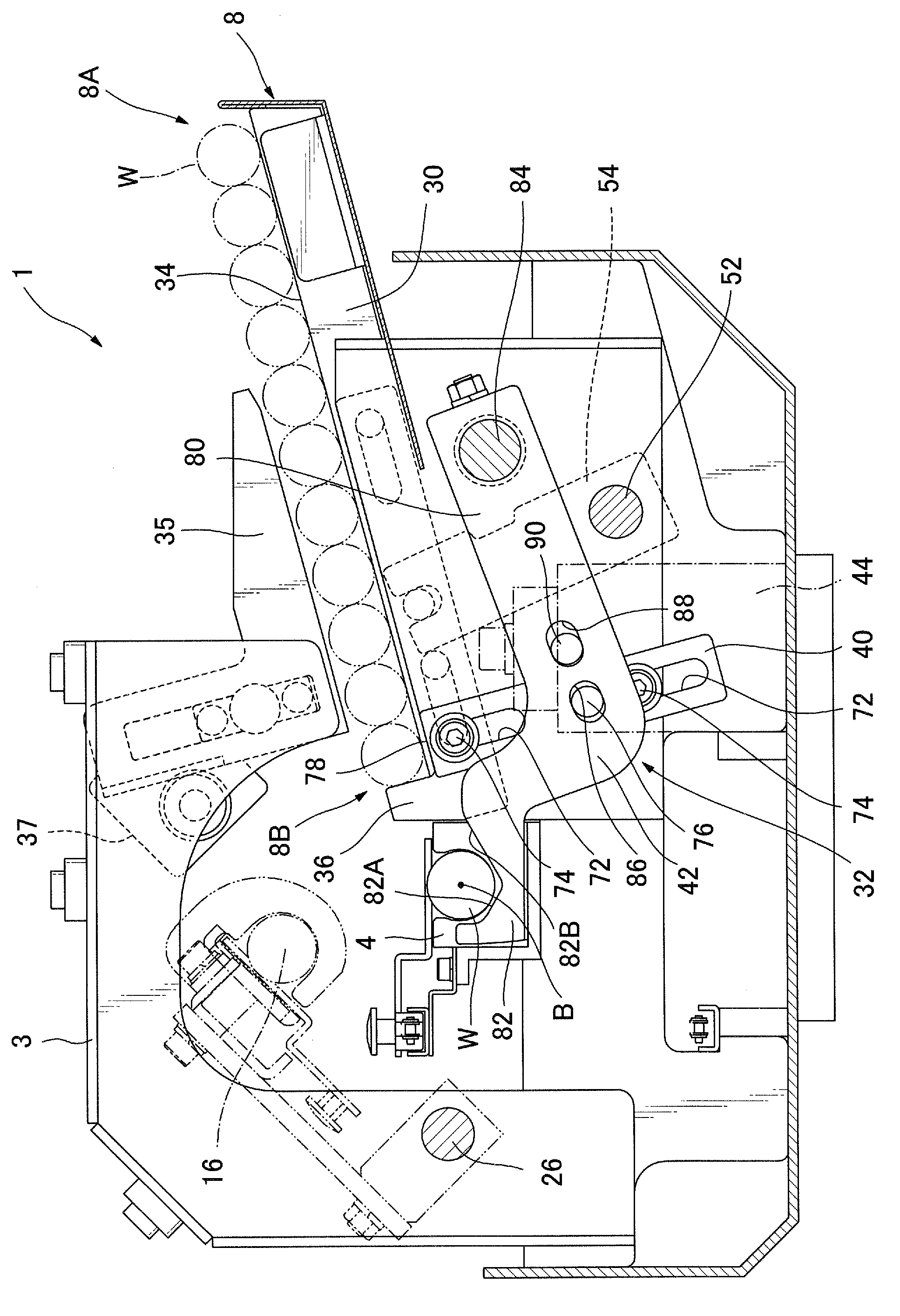
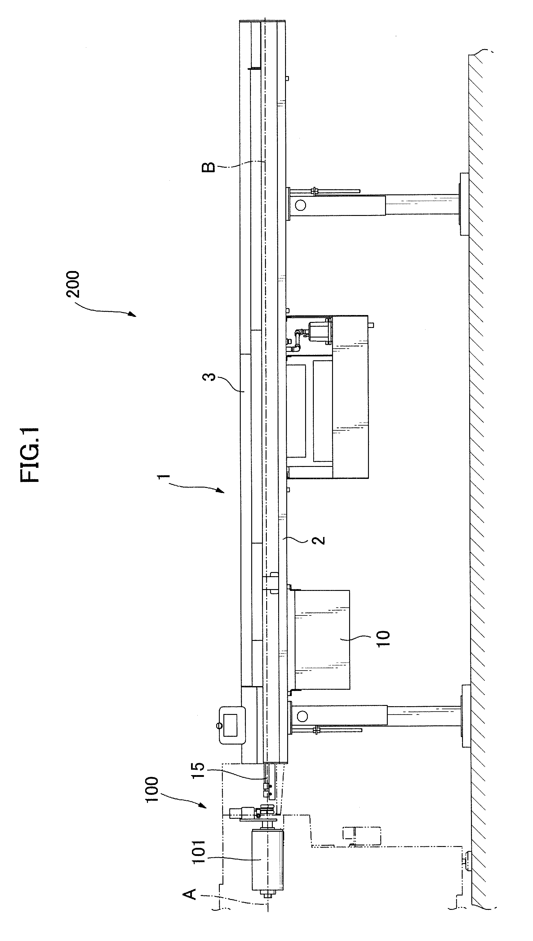
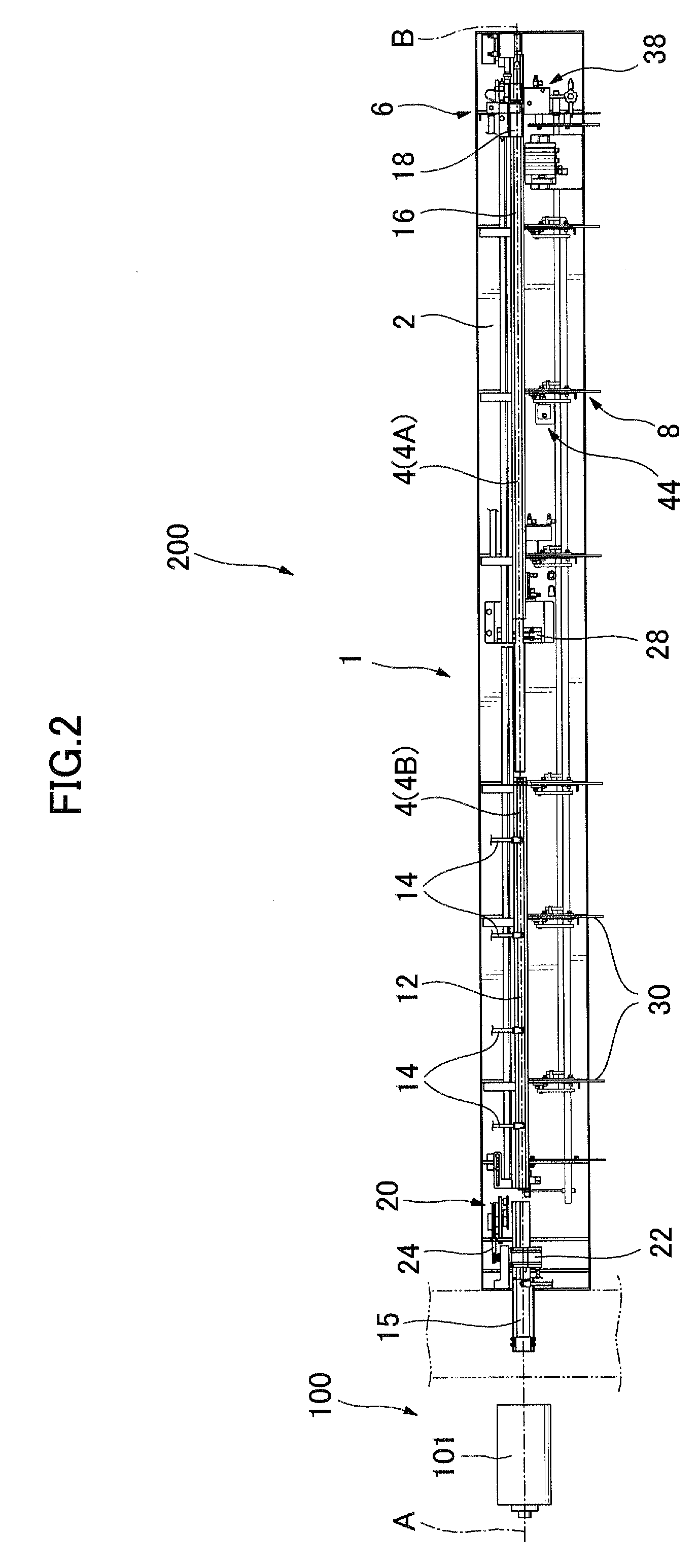
[0034]FIG. 1 is a general side view showing a bar feeder 1 according to one embodiment of the present invention, and FIG. 2 is a general top plan view showing the bar feeder 1 without a cover 3 covering an upper portion of the bar feeder 1 shown in FIG. 1.

[0035]The bar feeder 1 is disposed adjacent to a bar machining apparatus 100, and a bar machining system 200 is made up of the bar feeder 1 and the bar machining apparatus 100. For example, the bar machining apparatus 100 is a stationary main spindle-type NC lathe which comprises a headstock 101 including a main spindle A, and a machining section (not shown) for machining a bar piece supported by the headstock 101. The bar feeder 1 is adapted to feed bars W to the bar machining apparatus 100 one by one along a feed axis B aligned with the main spindle A.

[0036]In this embodiment, since the bar W is fed t...


PUM

PropertyMeasurementUnit
Diameteraaaaaaaaaa
Heightaaaaaaaaaa

Abstract

Disclosed is a bar feeder, which is capable of reliably loading a bar onto a guide rail with a simplified structure. The bar feeder 1 comprises a stock rack 8, a guide rail 4 for guiding a bar to a bar machining apparatus, and a bar supply mechanism 32 for taking bars W one by one out of the stock rack 8 and supplying the taken-out bar W onto the guide rail 4. The bar supply mechanism 32 includes a lifting member 40 adapted to lift a downstreammost one of the bar W on the stack rack 8, a bar receiving member 42 adapted to receive thereon the lifted bar W and supply the bar W onto the guide rail 4, and a stopper member 36 adapted to holds a second-downstreammost one of the bar W to be subsequently supplied. The lifting member 40 and the bar receiving member 42 are adapted to be driven by a common moving device 44, in such a manner that the lifting member 40 is linearly moved in an upward-downward direction in conjunction with a swing movement of the bar receiving member 42. The structure designed to drive the lifting member 40 and the bar receiving member 42 by the common moving device 44 makes it possible to reduce the number of components for a driving section, and achieve structural simplification.

Description

BACKGROUND OF THE INVENTION[0001]1. Field of the Invention[0002]The present invention relates to a bar feeder for automatically feeding a bar to a bar machining apparatus.[0003]2. Description of the Background Art[0004]As a conventional bar feeder, there has been known one type designed such that one of a plurality of pieces of bars placed on a stock rack is pushed upwardly by a lifting arm, and the lifted bar material is received by a bar transfer arm and transferred to a guide rail by swinging the bar transfer arm, as disclosed, for example, in the Japanese Utility Model 2505419. In this type of bar feeder, a bar material is received by the bar transfer arm and transferred to the guide rail. Thus, a shock against the guide rail is less than that in another type designed to perform a bar loading operation by dropping a bar material from the stock rack onto the guide rail. This makes it possible to reduce vibration and noise in the bar feeder.[0005]However, in the above bar feeder, ...

Claims


Application Information

Patent Timeline
IPC IPC(8): B23B3/00
CPCB23B13/10B23B13/02
Inventor HIROSAWA, KIYOSHIITO, TAKAZOSATO, KENJI
Owner IKURA SEIKI
Why Eureka
Try Eureka