Expansion valve with refrigerant flow dividing structure and refrigeration unit utilizing the same

a technology of refrigerant flow and expansion valve, which is applied in the direction of refrigeration components, mechanical equipment, light and heating equipment, etc., can solve the problems of increasing the cost and increasing the size of the expansion valve, and achieve the effect of effective deformation, preventing turbulence, and improving the flow dividing characteristic of the refrigeran

Inactive Publication Date: 2009-07-23
DAIKIN IND LTD
View PDF1 Cites 220 Cited by
  • Summary
  • Abstract
  • Description
  • Claims
  • Application Information

AI Technical Summary

Benefits of technology

[0009]In a conventional refrigerant flow divider, in order to perform the uniform division, a throttle is installed on the upstream side of a flow dividing tube attachment hole. However, since a throttle is also installed in an expansion valve disposed on an upstream side of a refrigerant flow divider, the same elements are installed in different parts, respectively. Meanwhile, in a conventional expansion valve, in order to reduce a refrigerant flow noise in an expansion valve, means for mitigating fluctuation in the velocity and pressure of a refrigerant flow is installed. However, due to the mitigating means, the size of the expansion valve increases, thereby increasing the cost.
[0010]It is an objective of the present invention to provide an expansion valve in which the structure of a refrigerant circuit which extends from an expansion valve to a refrigerant flow divider is simplified, and a discontinuous refrigerant flow noise is reduced in an expansion valve, thereby achieving a refrigerant flow dividing structure in which the flow dividing characteristic of the refrigerant of a refrigerant flow divider is improved. Another objective is to provide a refrigeration unit using the expansion valve.

Problems solved by technology

However, due to the mitigating means, the size of the expansion valve increases, thereby increasing the cost.

Method used


Image

  • Expansion valve with refrigerant flow dividing structure and refrigeration unit utilizing the same
  • Expansion valve with refrigerant flow dividing structure and refrigeration unit utilizing the same
  • Expansion valve with refrigerant flow dividing structure and refrigeration unit utilizing the same

Examples


tenth embodiment

[0140]Next, an expansion valve according to a tenth embodiment of the present invention will be described with reference to FIG. 10.

[0141]As shown in FIG. 10, the expansion valve is one in which the structure of the cylindrical portion of the ninth embodiment of the present invention is modified and includes a guide portion for reversing the direction of a flow of the refrigerant ejected from the cylindrical portion. A cylindrical portion 61 extends downwardly from the bottom surface of a partition wall 4 and is disposed coaxially with a first valve hole 7. Unlike the cylindrical portion of the ninth embodiment, a helical groove 61a is formed on an inner circumferential surface of the cylindrical portion 61. A guide portion 62 is installed on a wall surface opposite to a first throttle 10. The guide portion 62 serves to reverse the direction of a flow of the refrigerant ejected from the cylindrical portion 61. The guide portion 62 includes a conical protruding portion installed coax...

eleventh embodiment

[0143]Next, an expansion valve according to an eleventh embodiment of the present invention will be described with reference to FIG. 11.

[0144]As shown in FIG. 11, the expansion valve includes a porous permeable layer 59 inside a refrigerant flow dividing chamber 6, i.e., on the downstream side of a first throttle 10. The expansion valve includes the refrigerant flow dividing chamber 6 on the downstream side of the first throttle 10. The disk-shaped porous permeable layer 59 is installed inside the refrigerant flow dividing chamber 6. The porous permeable layer 59 is made of a material such as metal foam, ceramic, resin foam, mesh, and a porous plate.

[0145]In the expansion valve according to the eleventh embodiment of the present invention, a refrigerant flow is ejected to the refrigerant flow dividing chamber 6 after passing through the first throttle 10. As a result, the ejection energy of a refrigerant flow is dispersed. Thereafter, a refrigerant flow passes through the porous per...

twelfth embodiment

[0146]Next, an expansion valve according to a twelfth embodiment of the present invention will be described with reference to FIG. 12.

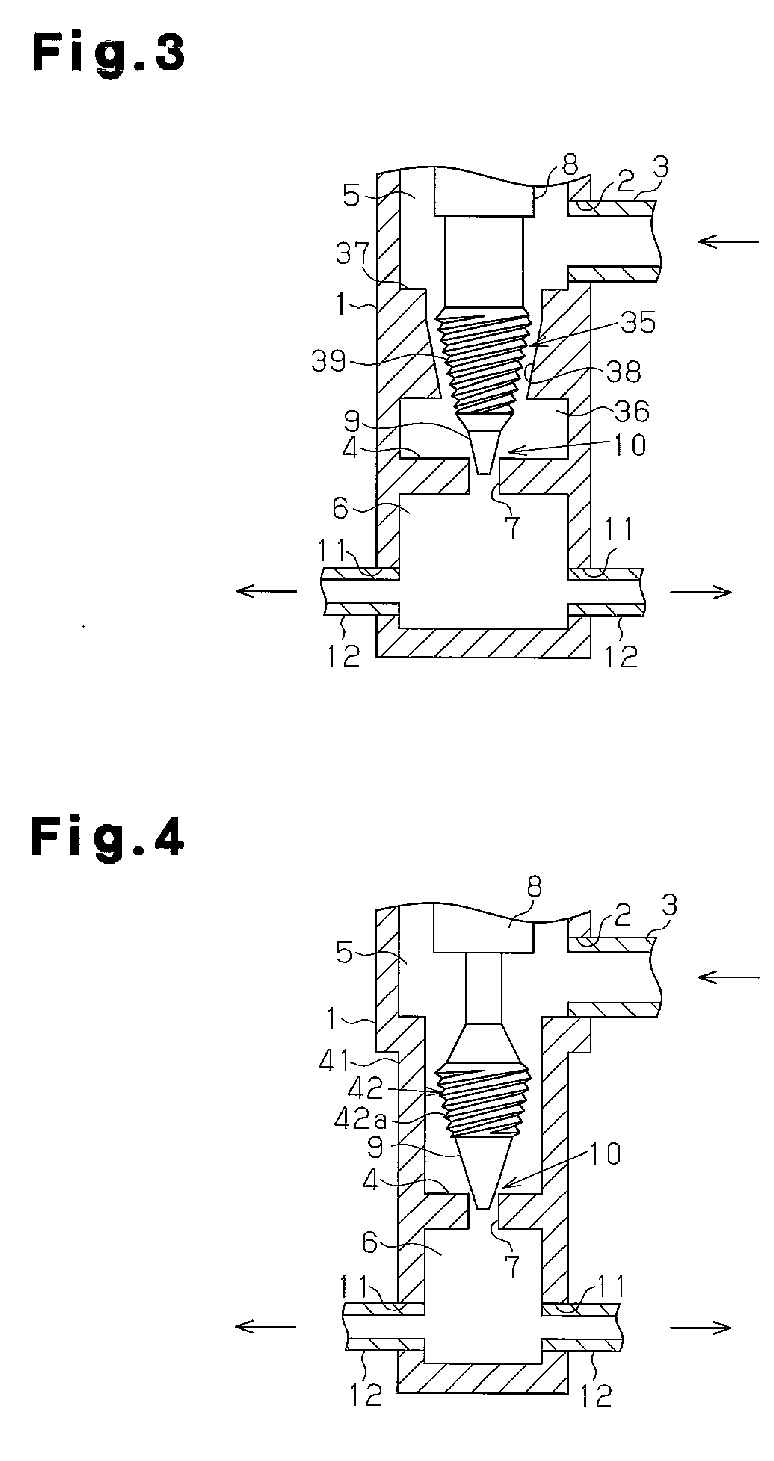
[0147]As shown in FIG. 12, in the expansion valve, an upstream side of a first throttle 10 is the same as that of the third embodiment, and a downstream side of the first throttle 10 is the same as that of the seventh embodiment. A second partition wall 37 is installed in a central portion of a valve chamber 5. An enlarged space portion 36 is formed between the second partition wall 37 and the first throttle 10. A tapered second valve hole 38 is formed at a center of the second partition wall 37, and a tapered second valve body 39 is formed in an intermediate portion of a valve rod 8. A helical passage is formed between an inner surface of a second valve hole 38 and an outer circumferential surface of the second valve body 39 as a second throttle 35.

[0148]A third partition wall 47 is installed on the downstream side of the first throttle 10. An enlarg...


PUM


Abstract

An expansion valve of the present invention has a structure which integrates a refrigerant flow divider. The expansion valve includes a refrigerant flow dividing chamber 6 on the downstream side of a first throttle 10. Flow dividing tubes 12 are connected to the refrigerant flow dividing chamber 6. In the expansion valve, refrigerant which has passed through the first throttle 10 is sprayed into the refrigerant flow dividing chamber 6, so that the flow dividing characteristic of the refrigerant is improved. Also, due to an enlargement of the passage in the refrigerant flow dividing chamber 6, the ejection energy of a flow of the refrigerant ejected from the first throttle 10 is dispersed, whereby a discontinuous refrigerant flow noise is reduced.

Description

TECHNICAL FIELD[0001]The present invention relates to an expansion valve with a refrigerant flow dividing structure and a refrigeration unit using the same.BACKGROUND ART[0002]In a refrigeration unit such as an air conditioner, a refrigerator, and a cooling device for manufacturing, in some cases, an evaporator includes a plurality of paths (refrigerant flow passages in a heat exchanger). For example, in a refrigerant circuit shown in FIG. 43, a refrigerant compressed by a compressor 201 is condensed in a condenser 202, and passes through a receiver 203 to be sent to an expansion valve 204. A refrigerant decompressed by the expansion valve 204 is sent to a refrigerant flow divider 206 through a refrigerant conduit 205 and is divided by the refrigerant flow divider 206 to be sent to a plurality of paths of an evaporator 207. A low-pressure refrigerant is evaporated in the evaporator 207 and then returns to the compressor 201 through an accumulator 208. In a case where the evaporator ...

Claims


Application Information

Patent Timeline
Patent Type & Authority Applications(United States)
IPC IPC(8): F25B41/04
CPCF25B39/028F25B2500/12F25B41/062F25B41/31F25B41/45F25B41/38
Inventor YUKIMOTO, TOORU
Owner DAIKIN IND LTD
Why Eureka
Try Eureka