Doubled cam shaft adjuster in layered construction

a technology of cam shaft and adjuster, which is applied in the direction of valve arrangement, yielding coupling, coupling, etc., can solve the problem of individual components tilting relative to one another, and achieve the effect of reducing the risk of individual components tilting

Inactive Publication Date: 2009-07-23
HILITE GERMANY
View PDF6 Cites 23 Cited by
  • Summary
  • Abstract
  • Description
  • Claims
  • Application Information

AI Technical Summary

Benefits of technology

[0018]The cam shaft adjuster, which is designed for controlling a double cam shaft, follows a layered construction. The cam shaft adjuster is equipped with a first rotor-type output body and a second rotor-type output body which are arranged parallel to each other with their rotary vane body parts. Each of the at least two output bodies has a receptacle which is designed for the reception, leading laterally out of the cam shaft adjuster center, of at least one cam shaft of the double cam shaft. A compensating element is provided for axially orienting at least one output body relative to the double cam shaft. The compensating element is an element which avoids tilting and deflection.
[0022]According to a further configuration, the compensating element can be an alignment spring which is in particular embodied in a dually spherical manner. The alignment spring allows lateral tilting-out of the output body in a cam shaft axial direction. The cam shaft axial direction is the direction in which the cam shaft extends. The alignment spring takes up very little space. An alignment spring is a part which is easy to install and to mount.
[0027]The valve drive may have only one drive wheel. The drive wheel may be configured as follows. The cam shaft adjuster has the one drive wheel. The drive wheel can for example be a chain wheel driven by the crank shaft. The valve drive thus has overall only one drive wheel driven by the crank shaft. The drive wheel is according to one configuration arranged on the side that is close to the cam shaft in such a way that a rotatable connection crown runs in synchronisation with the drive wheel for taking over and forwarding the hydraulic fluid to each chamber of the first and the second rotary vane adjuster. Only one connection crown is therefore provided, in order to minimise the number of components.
[0029]According to a further exemplary embodiment, the oil conveying channels can also be fed from an face of the cam shaft adjuster to the respective chambers of the different types (advance chamber and retard chamber) using an oil distributor. At least four channels are provided for this purpose. In one example embodiment, each channel has a length differing from the other channels. The channels open into the end-side chamber feed lines which can be configured in a planar manner. The conveyance of oil is likewise easy to establish and very reliable.

Problems solved by technology

Although this reference discloses the theoretical advantages, there are no proposals for a specific implementation.
The statement of object of U.S. Pat. No. 6,076,492 states that it is a problem, even in the case of simply constructed cam shaft adjusters of an axially displaceable type, to orient the cam shaft adjuster, the cylinder head, the control valve and the cam shaft in a stationary, permanent manner.
Even in the case of such sufficiently known cam shaft adjusters, there is a risk of the individual components tilting relative to one another.

Method used


Image

  • Doubled cam shaft adjuster in layered construction
  • Doubled cam shaft adjuster in layered construction
  • Doubled cam shaft adjuster in layered construction

Examples


Embodiment Construction

[0046]The ensuing detailed description provides exemplary embodiments only, and is not intended to limit the scope, applicability, or configuration of the invention. Rather, the ensuing detailed description of the exemplary embodiments will provide those skilled in the art with an enabling description for implementing an embodiment of the invention. It should be understood that various changes may be made in the function and arrangement of elements without departing from the spirit and scope of the invention as set forth in the appended claims.

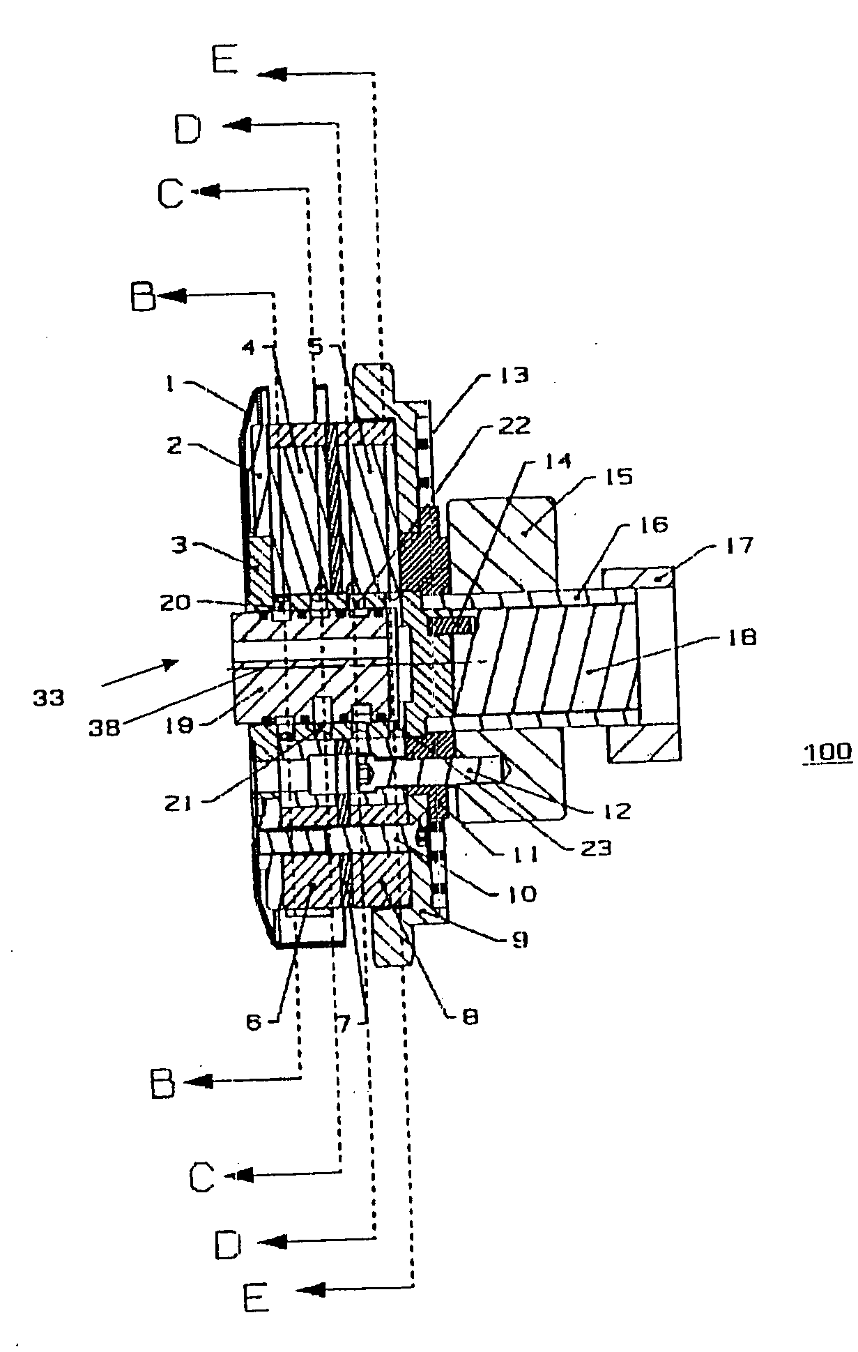
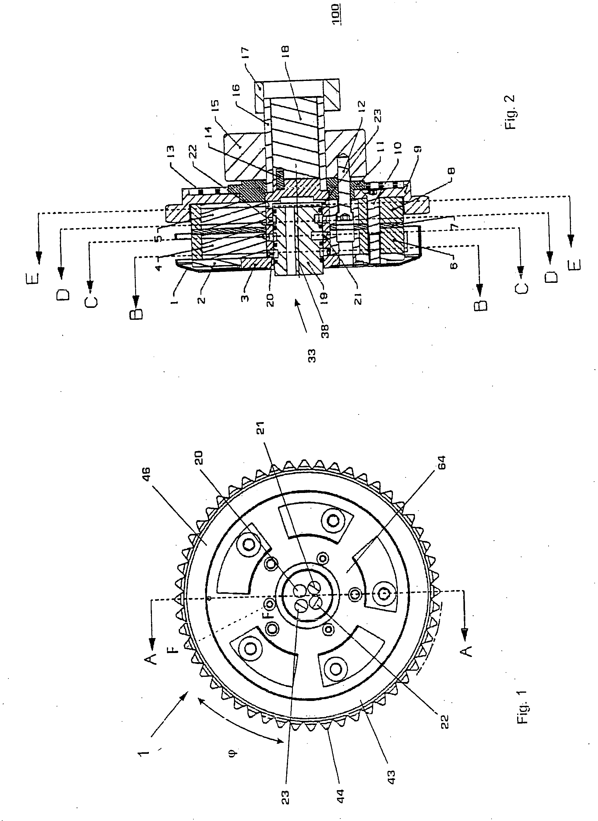
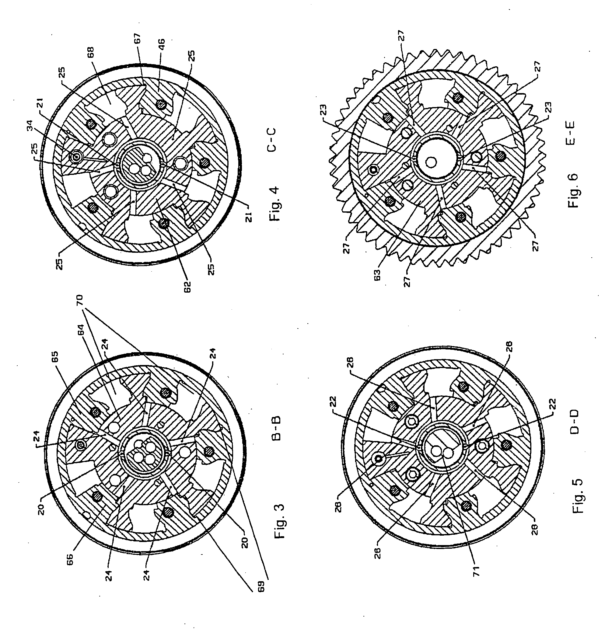
[0047]FIG. 1 shows an example cam shaft adjuster 1 in accordance with one embodiment of the present invention, which is configured as a rotary vane adjuster. The rotary vane adjuster can rotate within a certain angular range φ freely from one side to the second side. The rotation is caused by oil from feed line channels 20, 21, 22, 23 by means of which opposite chambers 67, 68 (see FIG. 4) can be acted on. The cam shaft adjuster 1, which is co...


PUM


Abstract

The present invention provides a cam shaft adjuster, which is designed for controlling a double cam shaft, which has a layered construction. The cam shaft adjuster is equipped with a first rotor-type output body and a second rotor-type output body which are arranged parallel to each other with their rotary vane body parts.

Description

[0001]This application claims the benefit of U.S. Provisional Patent Application No. 61 / 010,179, filed Jan. 4, 2008, which is incorporated herein and made a part hereof by reference.[0002]The present invention relates to a valve drive of an internal combustion engine with a doubled cam shaft.BACKGROUND OF THE INVENTION[0003]EP 1 347 154 A2 discloses a rotary drive designed for an adjustment shaft of a variable valve drive. A first rotatory, hydraulic drive is connected to a second rotatory, hydraulic drive in such a way as to allow rough and fine adjustment of the exact eccentric position within a valve drive chain. In other words, the angle of rotation position to be set is facilitated by a two-stage system.[0004]U.S. Pat. No. 2,911,956 describes a plate-shaped positioner by means of which a pivoting movement of a first plate influences the pivoting range of a second plate and so on.[0005]WO 01 / 12996 A1 shows in FIG. 5a a two-stator shaft adjustment system in which the rotor is res...

Claims


Application Information

Patent Timeline
Patent Type & Authority Applications(United States)
IPC IPC(8): F01L1/34
CPCF01L1/022F01L1/024F01L1/053F01L1/3442F01L2001/34493F01L2001/34469F01L2001/34483F01L2001/34489F01L2001/0473
Inventor KNECHT, ANDREASPOHL, DIRK
Owner HILITE GERMANY
Why Eureka
Try Eureka