Electrostatically atomizing device

Inactive Publication Date: 2009-07-23
PANASONIC CORP
View PDF3 Cites 51 Cited by
  • Summary
  • Abstract
  • Description
  • Claims
  • Application Information

AI Technical Summary

Benefits of technology

[0009]Also, the electrostatically atomizing device of the present invention preferably includes means for measuring conductivity of the liquid, such that the voltage applicator varies the voltage applied between the metal bodies i

Problems solved by technology

These metal ions can sterilize as a result harmful s

Method used


Image

  • Electrostatically atomizing device
  • Electrostatically atomizing device
  • Electrostatically atomizing device

Examples


Embodiment Construction

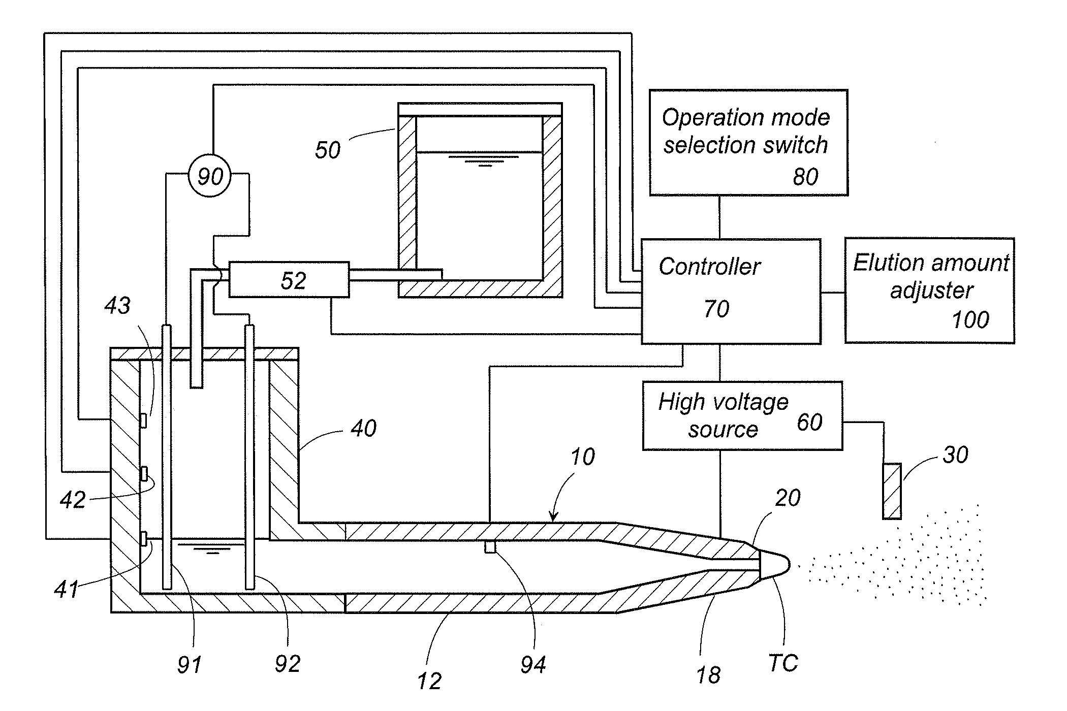
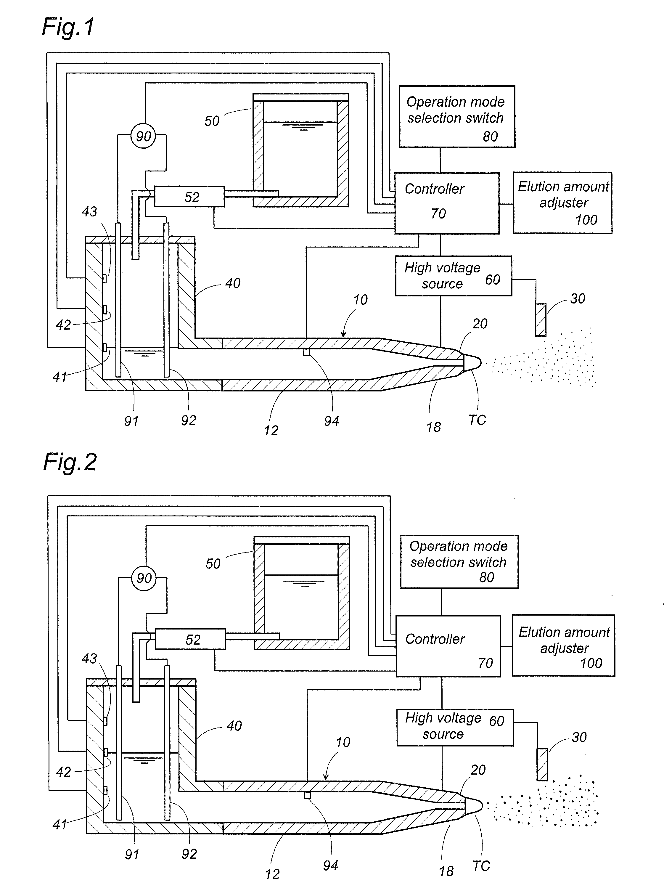
[0015]An electrostatically atomizing device according to an embodiment of the present invention is explained next with reference to FIGS. 1 and 2. The electrostatic atomizing device, for ejecting a mist of charged minute particles of a liquid, is configured so as to elute sterilizing metal ions into the charged minute particles that are to be ejected.

[0016]The electrostatically atomizing device comprises a carrier 10 the tip whereof constitutes an emitter electrode 20; an opposed electrode 30 disposed opposite the emitter electrode; a high voltage source 60 for applying a high voltage between the emitter electrode 20 and the opposed electrode 30; a controller 70; and an operation mode selection switch 80. The purpose of the operation mode selection switch 80 is to select a first operation mode in which there is generated only a mist of nanometer-size (3 nm to 100 nm) charged minute particles, and a second operation mode in which, in addition to a mist of nanometer-size charged minut...


PUM


Abstract

An electrostatic atomizing device for ejecting a mist of charged minute particles includes metal ion elution means for eluting sterilizing metal ions into a liquid to be electrostatically atomized. The metal ions are taken up by the charged minute particles, and are ejected into an environment space together with the charged minute particles, thereby eliciting a sterilizing effect. The elution amount of the metal ions is regulated by varying the voltage applied between two kinds of metal bodies.

Description

TECHNICAL FIELD[0001]The present invention relates to an electrostatically atomizing device for generating a mist of charged minute particles having sterilizing power.BACKGROUND[0002]Japanese Patent Application Laid-open No. H05-345156 discloses a conventional electrostatically atomizing device for generating charged minute particles of nanometer size (nanometer-size mist). In the device, a high voltage is applied across an emitter electrode, supplied with water, and an opposed electrode, to induce Rayleigh breakup of the water held on the emitter electrode, thereby atomizing the water. Such charged minute water particles, long-lived and containing active species (radicals), diffuse throughout an environment space, adhering to and / or penetrating into objects present in the space, so that these objects can be effectively sterilized and deodorized as a result.[0003]The mist of charged minute particles comprises active species (radicals), and hence the mist can potentially elicit a ste...

Claims


Application Information

Patent Timeline
IPC IPC(8): B05B5/03B05B5/16
CPCA61L2/22B05B5/1691B05B5/0255A61L9/14
Inventor SUDA, HIROSHINAKADA, TAKAYUKIMIYATA, TAKAHIROMACHI, MASAHARU
Owner PANASONIC CORP
Why Eureka
Try Eureka