
Dimming signal generation and methods of generating dimming signals

a technology of dimming signal and dimming signal, which is applied in the direction of electric variable regulation, process and machine control, instruments, etc., can solve the problems of limiting the ability to dim the leds to levels below, presenting difficulties in driving leds, and affecting the dimming effect of leds

Active Publication Date: 2009-07-23
IDEAL IND LIGHTING LLC
View PDF64 Cites 296 Cited by
  • Summary
  • Abstract
  • Description
  • Claims
  • Application Information

AI Technical Summary

Benefits of technology

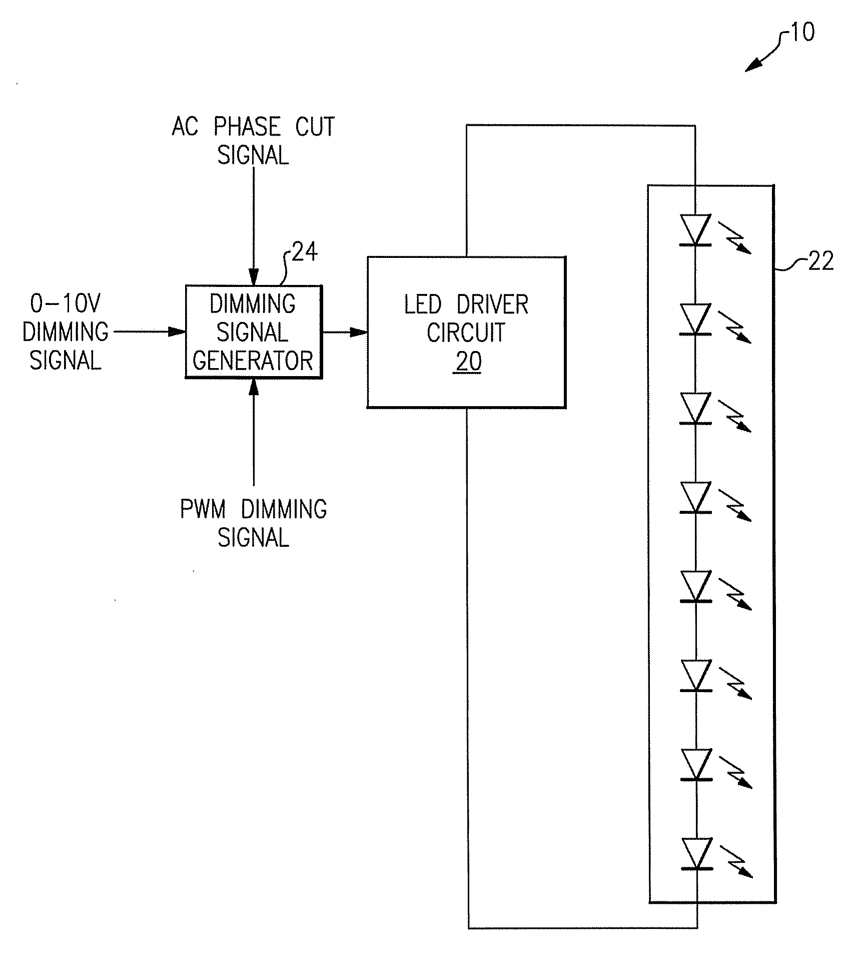
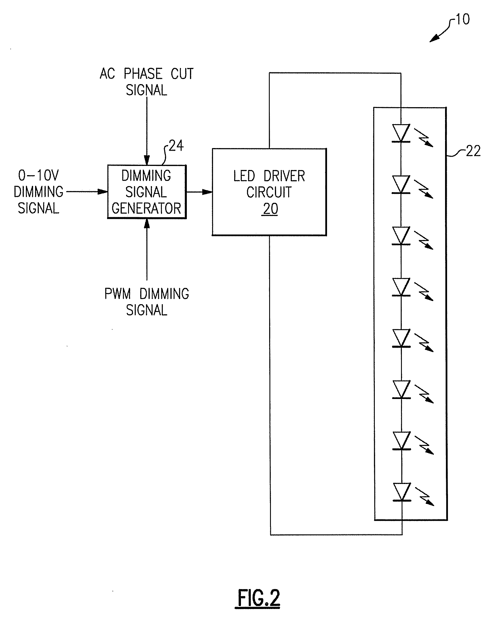
[0015]Some embodiments of the present inventive subject matter provide a lighting control circuit that comprises a dimming level detection circuit configurable to generate a first voltage level signal corresponding to a selected one of at least two different types of dimming signals. The types of dimming signals comprise at least two of an alternating current (AC) phase cut dimming signal, a direct current (DC) voltage level dimming signal or a pulse-width modulated (PWM) dimming signal. The circuit also includes a waveform generator configured to output a periodic waveform and a comparator circuit configured to compare the periodic waveform with the first voltage level signal to generate an output waveform having a duty cycle corresponding to a dimming level of the one of the at least two different input dimming signals and a frequency corresponding to the frequency of the periodic waveform.

Problems solved by technology

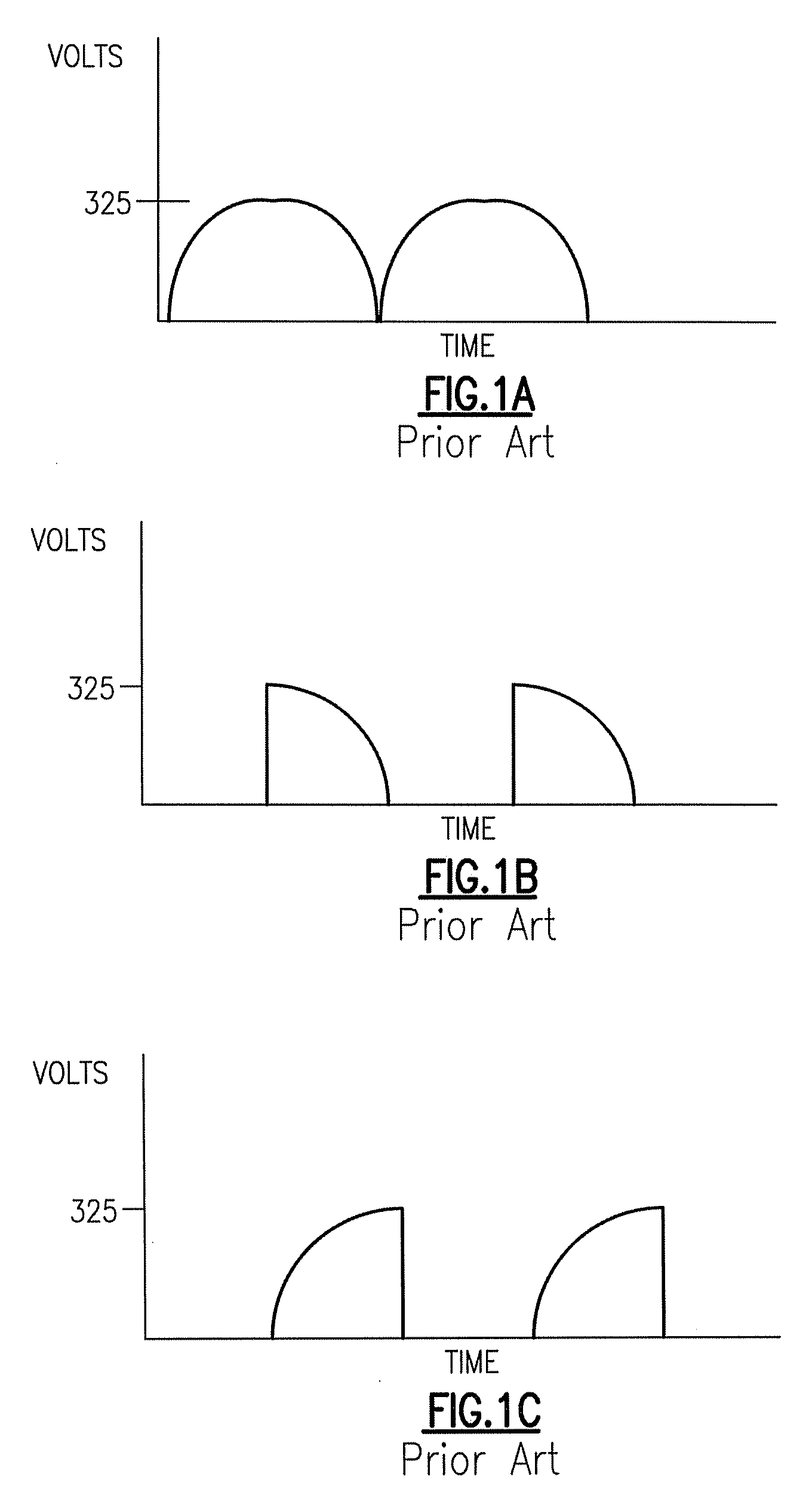
In particular, dimming that is based on varying the duty cycle of the line voltage may present several challenges in power supply design for solid state lighting.
This rapid response of LEDs may, in combination with conventional dimming circuits, present difficulties in driving LEDs.
This technique limits the ability to dim the LEDs to levels below where there is insufficient input power to energize the power supply.
This problem may be exacerbated in 50 Hz systems as the full wave rectified frequency of the AC line is only 100 Hz.
Furthermore, variation in the input signal may affect the ability to detect the presence of a phase cut dimmer or may make detection unreliable.
A further issue relates to AC dimmers providing some phase cut even at “full on.” If the LEDs are directly controlled by the AC pulse width, then the LEDs may never reach full output but will dim the output based on the pulse width of the “full on” signal.
This can result in a large dimming of output.
While this would result in a 5% decrease in output of an incandescent, it results in a 20% decrease in output if the phase cut signal is used to directly control the LEDs.

Method used


Image

  • Dimming signal generation and methods of generating dimming signals
  • Dimming signal generation and methods of generating dimming signals
  • Dimming signal generation and methods of generating dimming signals

Examples


Embodiment Construction

)

[0034]The present inventive subject matter now will be described more fully hereinafter with reference to the accompanying drawings, in which embodiments of the inventive subject matter are shown. However, this inventive subject matter should not be construed as limited to the embodiments set forth herein. Rather, these embodiments are provided so that this disclosure will be thorough and complete, and will fully convey the scope of the inventive subject matter to those skilled in the art. Like numbers refer to like elements throughout. As used herein, the term “and / or” includes any and all combinations of one or more of the associated listed items.

[0035]The terminology used herein is for the purpose of describing particular embodiments only and is not intended to be limiting of the inventive subject matter. As used herein, the singular forms “a”, “an” and “the” are intended to include the plural forms as well, unless the context clearly indicates otherwise. It will be further unde...


PUM


Abstract

A lighting control circuit comprises a dimming level detection circuit, a waveform generator and a comparator circuit. The dimming level detection circuit is configurable to generate a first voltage level signal corresponding to a selected one of at least two different types of dimming signals selected from among an AC phase cut dimming signal, a DC voltage level dimming signal or a PWM dimming signal. The waveform generator is configured to output a periodic waveform. The comparator circuit is configured to compare the periodic waveform with the first voltage level signal to generate an output waveform having a duty cycle corresponding to a dimming level of the one of the at least two different input dimming signals and a frequency corresponding to the frequency of the periodic waveform. Also, methods of controlling lighting.

Description

CLAIM OF PRIORITY[0001]The present Application claims priority from U.S. Provisional Patent Application Ser. No. 61 / 022,886 entitled “FREQUENCY CONVERTED DIMING SIGNAL GENERATION,” filed Jan. 23, 2008 and U.S. Provisional Patent Application Ser. No. 61 / 039,926 entitled “FREQUENCY CONVERTED DIMMING SIGNAL GENERATION,” filed Mar. 27, 2008, the disclosures of which are incorporated herein as if set forth in their entirety.RELATED APPLICATIONS[0002]The present application is related to U.S. patent application Ser. No. ______, entitled “Frequency Converted Dimming Signal Generation” filed concurrently herewith, the disclosure of which is incorporated herein as if set forth in its entirety.FIELD OF THE INVENTION(S)[0003]The present inventive subject matter relates to lighting devices and more particularly to power control for light emitting devices in the presence of a dimming signal.BACKGROUND OF THE INVENTION(S)[0004]Many control circuits for lighting utilize phase cut dimming. In phase...

Claims


Application Information

Patent Timeline
IPC IPC(8): H05B37/02H05B44/00
CPCH05B33/0815H05B39/044H05B33/0845H05B45/31H05B45/37H05B45/10H05B45/375H05B45/38
Inventor GIVEN, TERRYHARRISMYERS, PETER JAY
Owner IDEAL IND LIGHTING LLC
Learn More