
Image blur correction device, lens barrel and imaging apparatus

a technology of image blur correction and lens barrel, which is applied in the field of lens barrel and imaging apparatus, can solve the problems of increasing the size of the whole image blur correction device, the disadvantage of increasing the size of the image blur correction device and the lens device, and reducing so as to reduce the size of the whole devi

Inactive Publication Date: 2009-07-23
SONY CORP
View PDF2 Cites 74 Cited by
  • Summary
  • Abstract
  • Description
  • Claims
  • Application Information

AI Technical Summary

Benefits of technology

The present invention provides an image blur correction device that can be reduced in size in the optical axis direction of the correction lens and in the direction perpendicular to the optical axis direction of the correction lens. The device includes a correction lens, a movable frame, and a driving part. The movable frame holds the correction lens and is supported to be movable in two directions perpendicular to the optical axis direction of the lens. The driving part moves the movable frame in the first direction and the second direction to correct image blur. The device can be used in a lens barrel and an imaging apparatus. The technical effect of the invention is to reduce the size of the image blur correction device and the lens barrel, making them more portable and compact.

Problems solved by technology

Therefore, the whole image blur correction device is increased in size in a thickness direction (the optical axis direction of the correction lens) and the lens barrel on which the image blur correction device is mounted is increased in size, disadvantageously.
Therefore, an unnecessary space is formed on a side opposite to each of the driving sections across a correction lens in a plane perpendicular to an optical axis direction of the correction lens, so that the image blur correction device and the lens device are increased in size, disadvantageously.

Method used


Image

  • Image blur correction device, lens barrel and imaging apparatus
  • Image blur correction device, lens barrel and imaging apparatus
  • Image blur correction device, lens barrel and imaging apparatus

Examples


Embodiment Construction

[0041]An image blur correction device, a lens barrel and an imaging apparatus according to embodiments of the present invention will be described below with reference to the drawings; however, the present invention is not limited to the following embodiments.

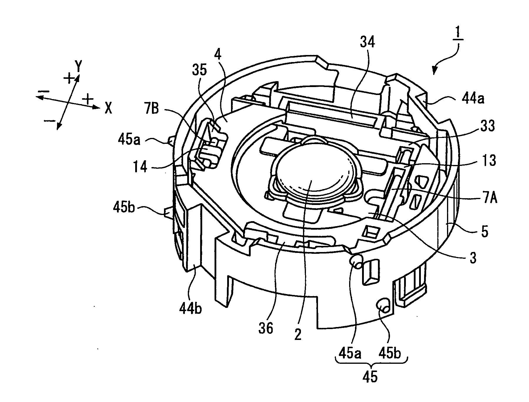
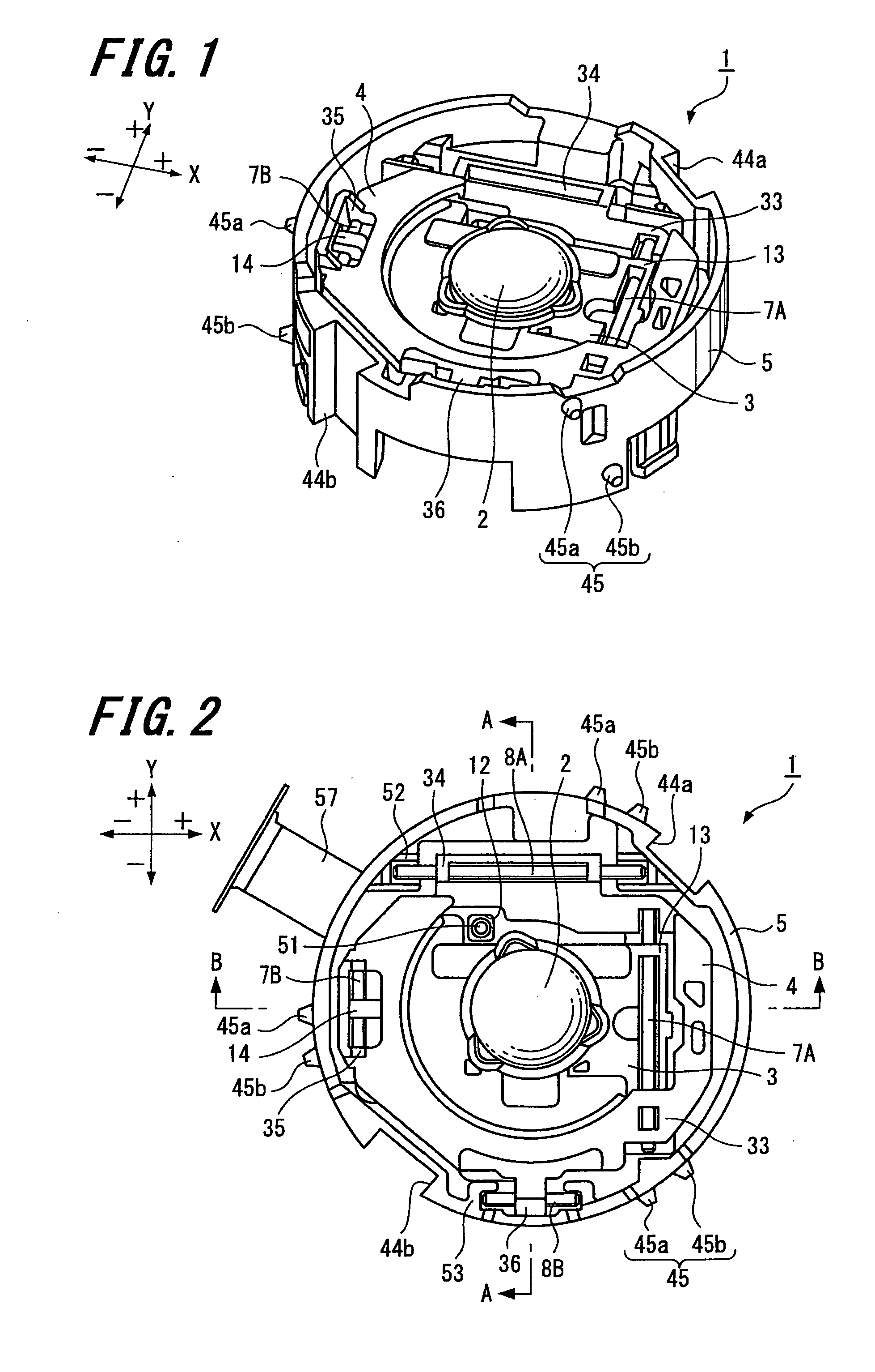
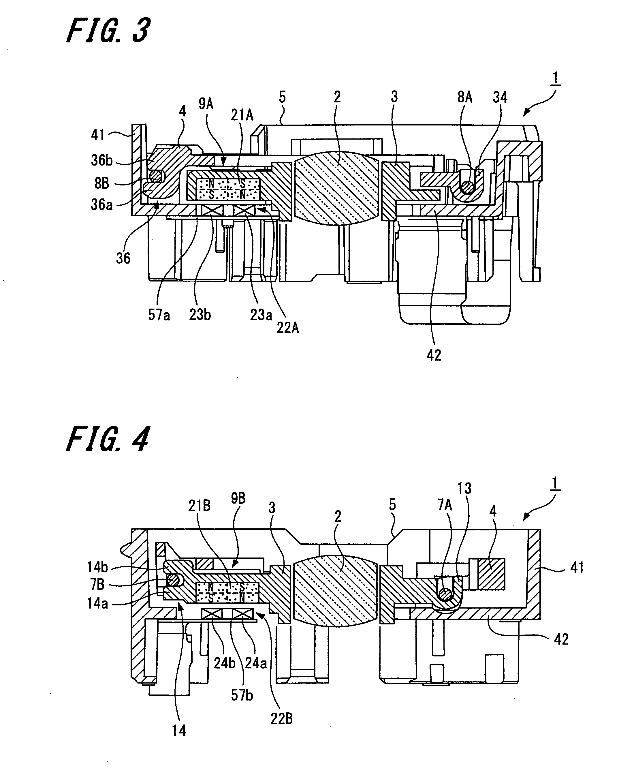
[0042]FIGS. 1 to 8 describe a first example of an image blur correction device according to an embodiment of the present invention. Specifically, FIG. 1 is a perspective view showing a first example of an image blur correction device according to an embodiment of the present invention. FIG. 2 is a plan view of the same. FIG. 3 is an A-A line cross-sectional view of the image blur correction device shown in FIG. 2. FIG. 4 is a B-B line cross-sectional view of the image blur correction device shown in FIG. 2. FIG. 5 is an exploded perspective view of the image blur correction device seen from one side. FIG. 6 is an exploded perspective view of the image blur correction device seen from another side. FIG. 7 is a plan view of a fixe...


PUM


Abstract

There is provided an image blur correction device including: a correction lens; a first movable frame; a second movable frame; a fixed frame; a first main guide shaft and a first auxiliary guide shaft; a second main guide shaft and a second auxiliary guide shaft; a first driving part; and a second driving part. The first auxiliary guide shaft is shorter than the first main guide shaft and the second driving part is placed between the first auxiliary guide shaft and the correction lens. The second auxiliary guide shaft is shorter than the second main guide shaft and the first driving part is placed between the second auxiliary guide shaft and the correction lens.

Description

CROSS REFERENCES TO RELATED APPLICATIONS[0001]The present invention contains subject matter related to Japanese Patent Application JP 2007-299673 filed in the Japanese Patent Office on Nov. 19, 2007, the entire contents of which being incorporated herein by reference.BACKGROUND OF THE INVENTION[0002]1. Field of the Invention[0003]The present invention relates to an image blur correction device correcting an image blur caused by vibration or the like during photographing, a lens barrel having the image blur correction device, and an imaging apparatus such as a digital still camera or video camera having the lens barrel.[0004]2. Description of the Related Art[0005]In recent years, performance of imaging apparatuses such as digital still cameras and video cameras has been remarkably improved, and thus still images and moving images may be easily captured by everyone with high image quality and high performance. Such improvement in performance of imaging apparatuses is largely due to im...

Claims


Application Information

Patent Timeline
Patent Type & Authority Applications(United States)
IPC IPC(8): G03B17/00G02B27/64H04N23/40
CPCG02B7/023G03B5/00G03B2205/0007G03B2205/0069H04N5/23287G02B27/646H04N5/23248H04N23/68H04N23/687
Inventor TSUTSUMI, TAKUYAMAEDA, YUTAKA
Owner SONY CORP
Learn More