Rechargeable battery

a rechargeable battery and terminal hole technology, applied in the field of rechargeable batteries, can solve the problems of increasing the thickness of the cap plate, difficulty in directly forming a bend at the cap plate, and the discharge of the rechargeable battery, so as to improve the sealing performance between the electrode terminals and the cap plate, improve the sealing performance of the terminal hole, and improve the sealing performance.

Inactive Publication Date: 2009-07-23
SAMSUNG SDI CO LTD
View PDF9 Cites 116 Cited by
  • Summary
  • Abstract
  • Description
  • Claims
  • Application Information

AI Technical Summary

Benefits of technology

[0023]According to an exemplary embodiment of the present invention, a sealing reinforcing member is formed on a circumference of a terminal hole to enlarge a contact area of a gasket and a terminal hole. Therefore, sealing performance between the electrode terminals and the cap plate is improved.
[0024]According to an exemplary embodiment of the present invention, a protrusion is formed on a circumference of a sealing reinforcing member. The protrusion protrudes downwardly and pressurizes a gasket. Therefore, sealing performance between a cap plate and a gasket is further improved.
[0025]According to an exemplary embodiment of the present invention, an elastic deformation protrusion is formed on an interior circumference of a terminal hole to have a thickness that is thinner than a periphery thereof. Therefore, sealing performance of the terminal hole is further improved.
[0026]According to an exemplary embodiment of the present invention, a fixing groove is formed on a bottom side of a cap plate to receive a protrusion formed at a gasket, and the fixing groove prevents the gasket from rotating.

Problems solved by technology

When the swelling occurs, a rechargeable battery may explode due to the increased internal pressure.
It is difficult to directly form a bend at the cap plate because the thickness of the cap plate increases.
If the thickness of the cap plate is reduced to directly form a vent on the cap plate, the sealing of the case cannot be made as well at the terminal hole because a contact area of the terminal hole and a gasket may be too small.
If the terminal hole is not completely sealed, electrolyte solution stored in the case may flow out, thereby shorting rechargeable batteries.

Method used


Image

  • Rechargeable battery
  • Rechargeable battery
  • Rechargeable battery

Examples


Embodiment Construction

[0035]Hereinafter, exemplary embodiments of the present invention will be described in detail with reference to the accompanying drawings so that those skilled in the art to which the present invention pertains can realize the present invention. As those skilled in the art would realize, the described embodiments may be modified in various different ways, all without departing from the spirit or scope of the present invention. Like reference numerals designate like elements throughout the specification.

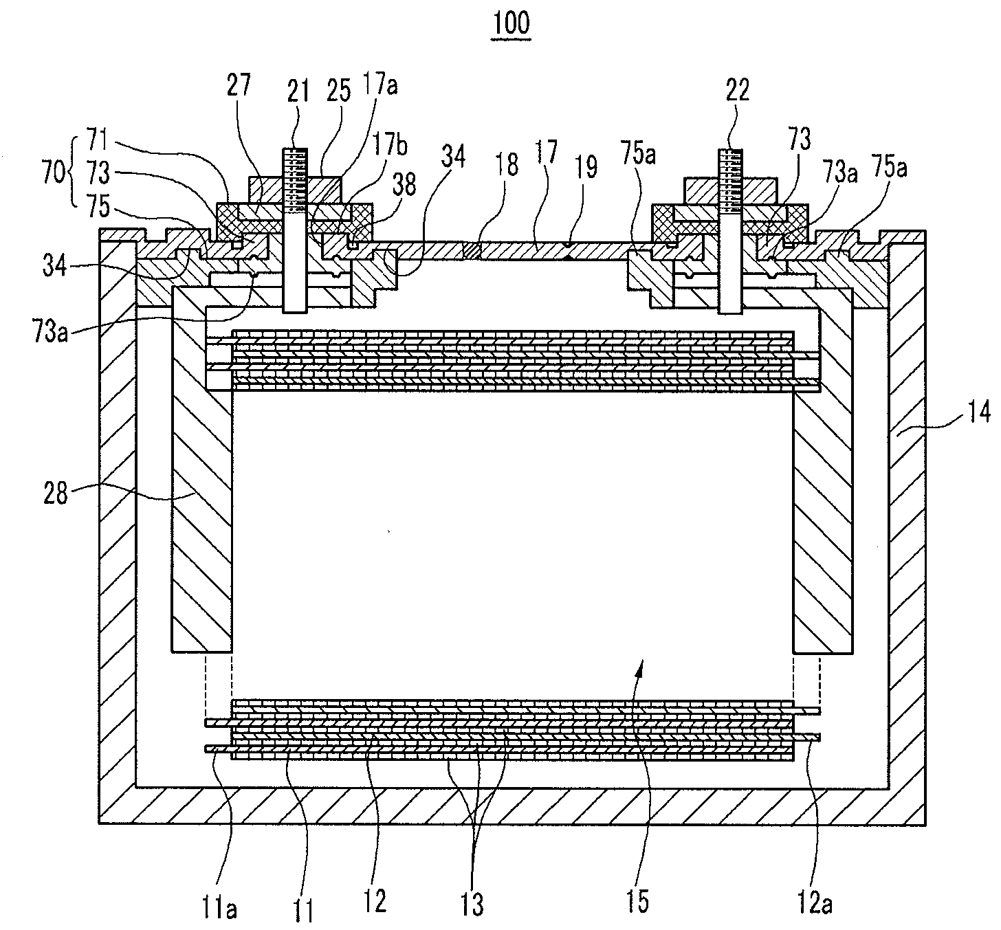
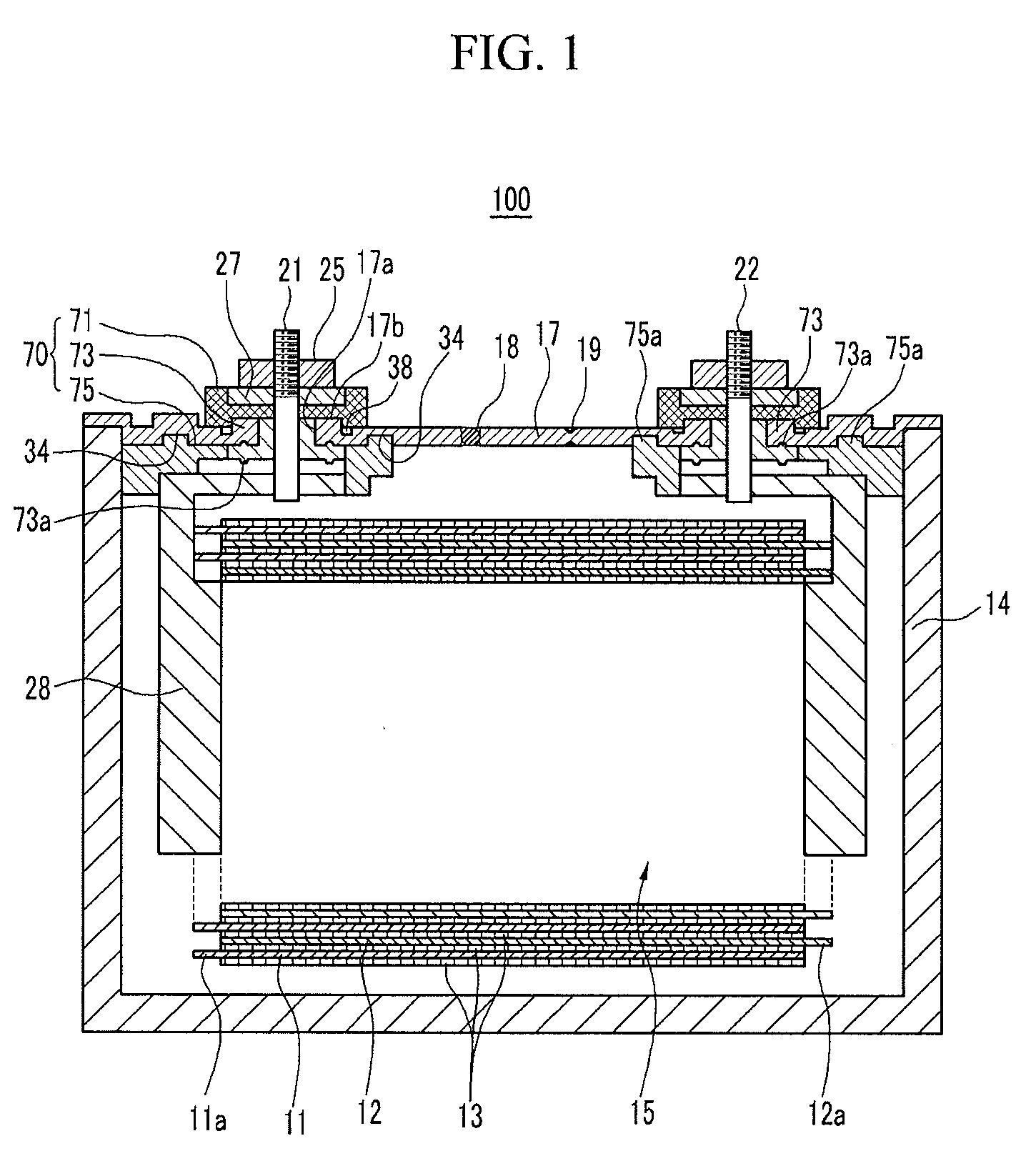
[0036]FIG. 1 is a cross-sectional view illustrating a rechargeable battery according to the first exemplary embodiment of the present invention.

[0037]Referring to FIG. 1, a rechargeable battery 100 includes an electrode assembly 15 having an anode 11 and a cathode 12 wound with a separator 13 interposed therebetween as an insulator. The battery 100 also includes a case 14 for housing the electrode assembly 15, and electrode terminals 21 and 22 which includes a positive terminal 21 and...


PUM

PropertyMeasurementUnit
thicknessaaaaaaaaaa
circumferenceaaaaaaaaaa
elastic deformationaaaaaaaaaa

Abstract

The present invention relates to a rechargeable battery. The rechargeable battery includes an electrode assembly, a case, electrode terminals, and a cap plate. The electrode assembly includes a separator and an anode and a cathode disposed at both sides of the separator. The case houses the electrode assembly. The electrode terminals are electrically connected to the electrode assembly and protrude outwardly from the case. The cap plate closes and seals the case. The cap plate includes a terminal hole for receiving the electrode terminals and a sealing reinforcing member formed along a circumference of the terminal hole and having a greater thicker than a periphery thereof.

Description

CROSS-REFERENCE TO RELATED APPLICATION[0001]This application claims priority to and the benefit of Korean Patent Application No. 10-2008-0007155 filed in the Korean Intellectual Property Office on Jan. 23, 2008, the entire content of which is incorporated herein by reference.BACKGROUND OF THE INVENTION[0002]1. Field of the Invention[0003]The present invention relates to a rechargeable battery. More particularly, the present invention relates to a rechargeable battery including a cap plate with an improved structure.[0004]2. Description of the Related Art[0005]A rechargeable battery can be repeatedly charged and discharged, unlike a primary battery that is incapable of being recharged. A low capacity rechargeable battery has been used for small electronic devices such as a mobile phone, a laptop computer, and a camcorder, and a large capacity battery has been widely used as a power source for driving a motor of a hybrid vehicle.[0006]Recently, a high power rechargeable battery assemb...

Claims


Application Information

Patent Timeline
Patent Type & Authority Applications(United States)
IPC IPC(8): H01M2/02H01M50/147H01M50/176H01M50/55H01M50/553
CPCH01M2/043H01M2/30H01M2/06Y02E60/10H01M50/147H01M50/55H01M50/553H01M50/176H01M50/103H01M50/183
Inventor KIM, YONG-SAMKOGURE, MASANORI
Owner SAMSUNG SDI CO LTD
Why Eureka
Try Eureka