Fuel cell

a fuel cell and knock pin technology, applied in the field of fuel cells, can solve the problems of inefficiency in assembly of fuel cells, inability to achieve desired sealing performance, and laborious operation of inserting knock pins into the holes of unit cells, and achieve the effect of easy assembly

Inactive Publication Date: 2008-01-29
HONDA MOTOR CO LTD
View PDF10 Cites 2 Cited by
  • Summary
  • Abstract
  • Description
  • Claims
  • Application Information

AI Technical Summary

Benefits of technology

[0015]A main object of the present invention is to provide a fuel cell with a compact and simple structure in which unit cells are reliably fastened together, and the fuel cell can be assembled easily.
[0017]Since the metal clip member has relatively long first and second holding portions, the outer regions of first and second separators are securely fastened by the first and second holding portions. Therefore, it is possible to effectively prevent the metal clip member from being detached from the first and second separators. The first and second holding portions are long in comparison with the side plate of the metal clip member. The first and second holding portions have the elasticity to securely tighten the first and second separators. Thus, the unit cell can be assembled efficiently, and the number of steps for assembling the unit cell is small. The sealing performance can be maintained in handling the unit cell, and the unit cell can be handled efficiently. In the unit cell, the membrane electrode assembly is interposed between the first and second separators. The humidity at the membrane electrode assembly is kept at a desired level. The membrane electrode assembly is not dried, and the desired performance of the unit cell is maintained.
[0020]Each of the first and second separators may include a metal plate and an insulating section of insulating resin or insulating coating formed at an outer end of the metal plate. The metal clip member is attached to the insulating section of the first separator and the insulating section of the second separator. With the simple and inexpensive structure, the short circuit between the first and second separators through the metal clip member is prevented, and the desired power generation performance can be maintained.
[0021]The first and second separators may include curved ends, respectively. The curved ends of the first and second separators are curved or bent away from each other at the insulating sections of the first and second separators. Therefore, it is possible to effectively prevent the metal clip member from being detached from the first and second separators.
[0022]The curved end may include the insulating section of insulating resin or insulating coating formed at the outer end of the metal plate. In this case, the structure of the curved end is simple.

Problems solved by technology

When a large number of the unit cells are stacked together, the operation of inserting the knock pins into the holes of the unit cells is laborious, and the fuel cell can not be assembled efficiently.
Positional displacement between components may occur undesirably, and the desired sealing performance may not be achieved.
Thus, when a large number of unit cells 2 are stacked together, operation of assembling the holding pins 6 and the snap rings 7 is considerably laborious, and can not be performed efficiently.
Therefore, the fuel cell is large and heavy.

Method used


Image

  • Fuel cell
  • Fuel cell
  • Fuel cell

Examples


first embodiment

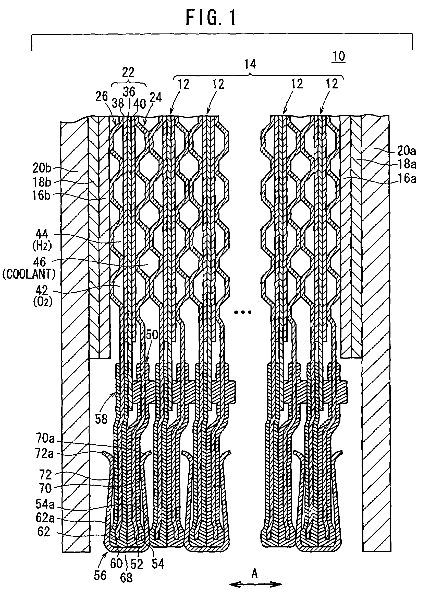
[0034]FIG. 1 is a view schematically showing a fuel cell 10 according to the present invention.

[0035]The fuel cell 10 includes a stacked body 14 formed by stacking a plurality of unit cells 12 in a direction indicated by an arrow A. Terminal plates 16a, 16b are provided on the outermost unit cells 12 at opposite ends of the stacked body 14, respectively. Insulating plate 18a, 18b are provided on the terminal plates 16a, 16b, respectively. Further, end plates 20a, 20b are provided on the insulating plates 18a, 18b, respectively. The end plates 20a, 20b are fastened by tie rods or the like (not shown) for tightening the unit cells 12 of the fuel cell 10 with a predetermined tightening force in the direction indicated by the arrow A.

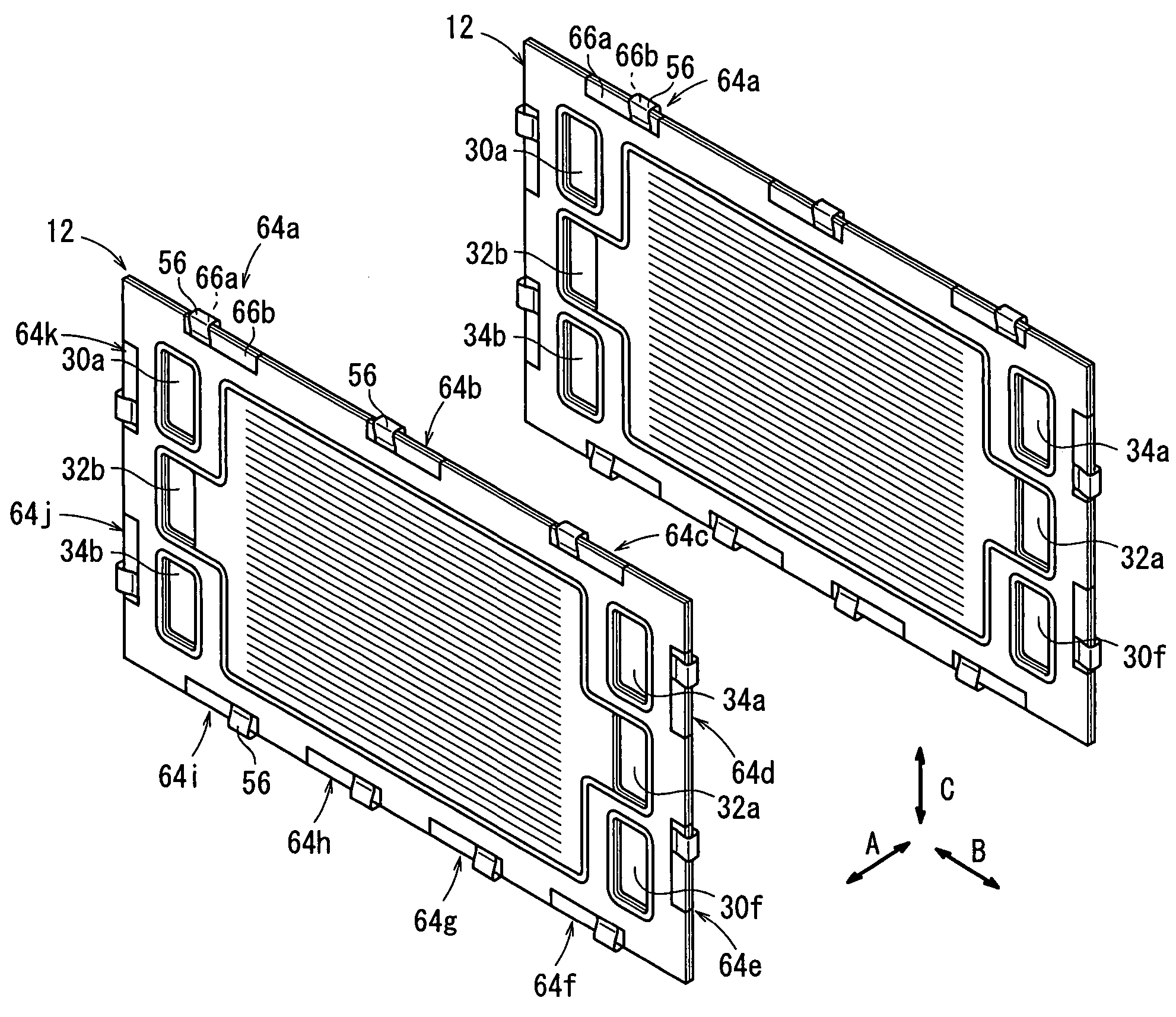
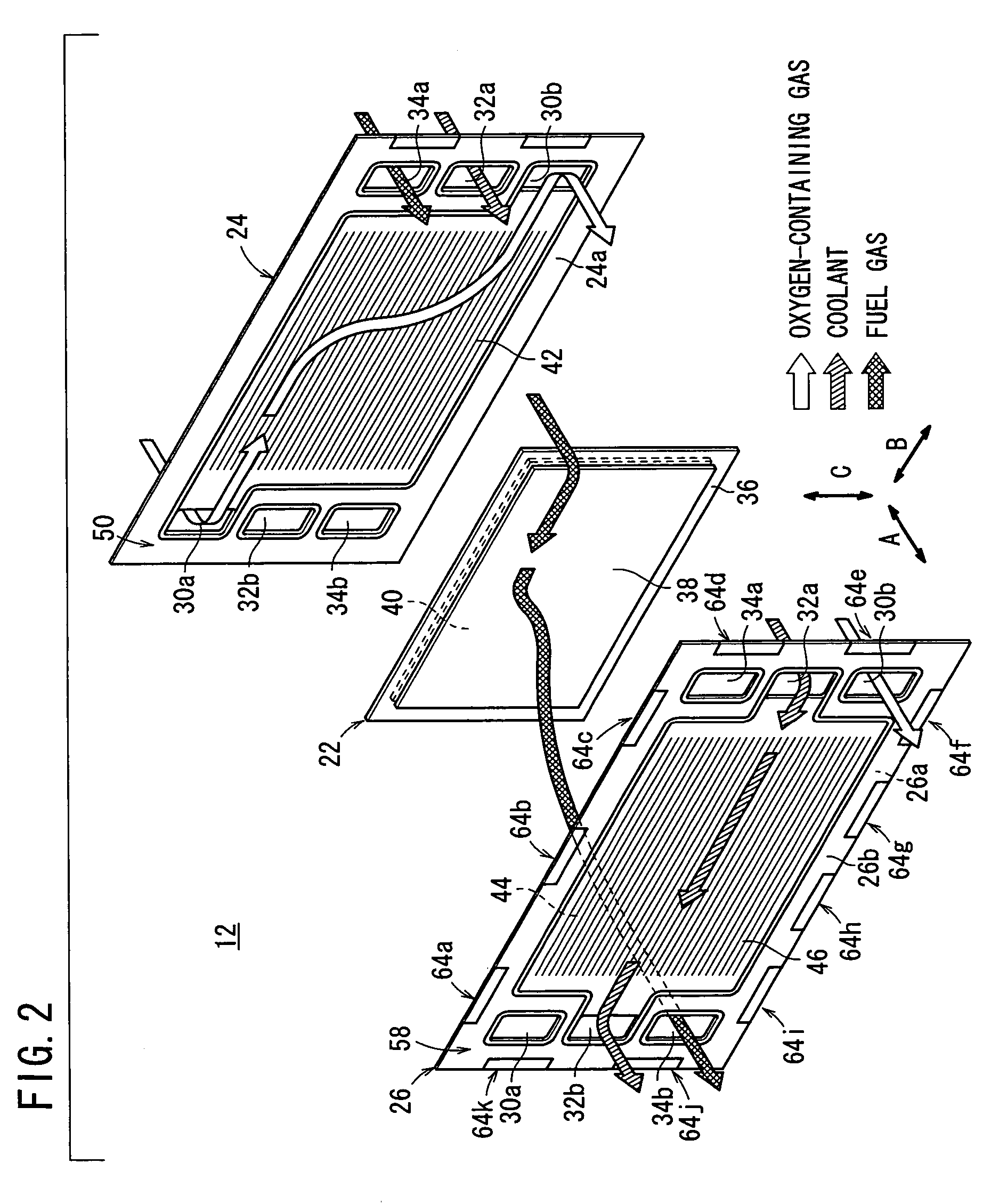
[0036]As shown in FIG. 2, the unit cell 12 includes a membrane electrode assembly (electrolyte electrode assembly) 22 and first and second metal separators 24, 26 for sandwiching the membrane electrode assembly 22.

[0037]At one horizontal end of the unit cel...

second embodiment

[0071]FIG. 7 is a perspective view showing a metal clip member 80 of a fuel cell according to the present invention.

[0072]The metal clip member 80 includes a side plate 82 and first and second holding portions 84, 86. The side plate 82 is curved at opposite ends, and the first and second holding portions 84, 86 are extending from the opposite ends of the side plate 82. The dimension H1 of the first and second holding portions 84, 88 is greater than the dimension (width) H2 of the side plate 82. Edges 84a, 86a of the first and second holding portions 84, 86 are curved or bent away from each other. The edges 84a, 86a protrude from opposite sides in a direction indicated by the arrow W for a predetermined distance.

[0073]Thus, the dimension of the edges 84a, 86a of the holding portions 84, 86 in the direction indicated by the arrow W is long, and the first and second metal separators 24, 26 are securely held between the edges 84a, 86a of the holding portions 84, 86.

third embodiment

[0074]FIG. 8 is a perspective view showing a metal clip member 90 of a fuel cell according to the present invention.

[0075]The metal clip member 90 includes a side plate 92, and first and second holding portions 94, 96. The side plate 92 is curved at opposite ends, and the first and second holding portions 94, 96 are extending from the opposite ends of the side plate 92. The length of the first and second holding portions 94, 96 is greater than the length of the side plate 92. A relatively large opening 98 is formed centrally in each of the first and second holding portions 94, 96. Edges 94a, 96a of the first and second holding portions 94, 96 are curved or bent away from each other.

[0076]Since the relatively large openings are formed in the first and second portions 94, 96 of the metal clip member 90, the metal clip member 90 has the lightweight. The overall weight of the fuel cell is small. In particular, when a large number of the unit cells 12 are stacked together, the weight of ...


PUM

PropertyMeasurementUnit
lengthaaaaaaaaaa
unit cellaaaaaaaaaa
distanceaaaaaaaaaa

Abstract

A fuel cell includes a plurality of metal clip members for holding outer regions of first and second metal separators at a plurality of positions. Each of the metal clip member includes a side plate and first and second holding portions. The side plate is curved at opposite ends, and the first and second holding portions are extending from the opposite ends of the side plate. The first and second holding portions generates a predetermined elastic force for holding the first and second metal separators. The outer ends of the first and second metal separators are covered by insulating sections, and the insulating sections are held between the first and second holding portions so that the entire unit cell is tightened by the predetermined elastic force.

Description

BACKGROUND OF THE INVENTION[0001]1. Field of the Invention[0002]The present invention relates to a fuel cell including at least one unit cell. The unit cell includes an electrolyte electrode assembly, and first and second separators for sandwiching the electrolyte electrode assembly. The electrolyte electrode assembly includes a pair of electrodes and an electrolyte interposed between the electrodes.[0003]2. Description of the Related Art[0004]For example, a solid polymer electrolyte fuel cell employs a membrane electrode assembly (MEA) which includes two electrodes (anode and cathode), and an electrolyte membrane interposed between the electrodes. The electrolyte membrane is a polymer ion exchange membrane. The membrane electrode assembly is interposed between a pair of separators. The membrane electrode assembly and the separators make up a unit cell for generating electricity.[0005]In the unit cell, a fuel gas (reactant gas) such as a gas chiefly containing hydrogen (hydrogen-con...

Claims


Application Information

Patent Timeline
Patent Type & Authority Patents(United States)
IPC IPC(8): H01M2/00H01M2/02H01M2/08H01M2/14H01M8/02H01M8/10H01M8/24
CPCH01M8/02H01M8/241H01M8/0297H01M8/249H01M2008/1095Y02E60/50H01M8/0267H01M8/242H01M8/2457H01M8/2483
Inventor SUGIURA, SEIJISUZUKI, RYUGOSUGITA, NARUTOSHITANAKA, HIROYUKIKUWAYAMA, TAKASHI
Owner HONDA MOTOR CO LTD
Why Eureka
Try Eureka