Rotating fluid machine

a technology of rotating fluid machine and rotating shaft, which is applied in the direction of machines/engines, positive displacement liquid engines, piston pumps, etc., can solve the problems of insufficient performance of expansion machine, further reduction of sealing performance, and difficulty in ensuring sealing performan

Inactive Publication Date: 2008-05-06
HONDA MOTOR CO LTD
View PDF9 Cites 2 Cited by
  • Summary
  • Abstract
  • Description
  • Claims
  • Application Information

AI Technical Summary

Benefits of technology

[0013]With the first feature, the fixed side valve plate is non-rotatably supported to float at the valve body portion fixed to the casing, the high-pressure working medium is supplied to the pressure chamber formed in the valve body portion to open to the mating surface with the fixed side valve plate, and the mating surface is sealed by the seal member to receive the pressure of the high-pressure working medium. Consequently, the pressing load to press the fixed side valve plate to the slide surface with the movable side valve plate is generated with the pressure of the working medium of the pressure chamber to bring the slide surface into close contact therewith, to prevent leakage of the working medium. The fixed side valve plate is made to follow oscillation of the slide surface by the floating support to enhance following performance of the pressing load to the slide surface, and thereby sealing performance of the slide surface can be secured.
[0047]With the seventeenth feature, the pressing member is made of metal, and therefore when the pressure chamber has a high temperature, the pressing member is thermally expanded and presses the seal member more firmly, thereby making it possible to further enhancing the sealing performance.

Problems solved by technology

At this time, it is difficult to secure sealing performance with the pressing member following the swing of the slide surface by only biasing the pressing member with a resilient force of the spring, pressure of the combustion gas, pressure of a supply gas at high temperature and high pressure or pressure of steam to bring the pressing member into close contact with the slide surface.
However, when the pressure of the working medium does not rise sufficiently just after the start of the expansion machine, the seal member cannot exhibit the sufficient sealing function due to insufficient pressure, and if a foreign matter such as an oxidized scale is contained in the working medium, the seal member is damaged, and the sealing performance is further reduced, which brings about the possibility that the expansion machine cannot exhibit sufficient performance.
The movable side valve plate provided at the rotor inevitably oscillates a little.
If the fixed side valve plate in contact with the movable side valve plate via the slide surface oscillates, there is the possibility that the close contact of a seat surface of the fixed side valve plate and a lip of the seal member is impaired and steam leaks out of this portion to make it impossible for the expansion machine to exhibit sufficient performance.
When the pressure of the working medium supplied to the pressure chamber is low, the outer periphery surface of the V-packing cannot be firmly pressed against an inner periphery surface of the pressure chamber, and the working medium sometimes leaks out of the pressure chamber due to reduction in the sealing function.
Once this leakage occurs, the leakage cannot be stopped even if the pressure of the working medium increases, and therefore it is necessary to stop the operation of the expansion machine and restart it thereafter.
However, since it is difficult to bias the V-packing outward in the radial direction with the coil spring placed in the axial direction and the resilient force of the coil spring reduces when the working medium is at high temperature, a sufficient effect cannot be expected.

Method used


Image

  • Rotating fluid machine
  • Rotating fluid machine
  • Rotating fluid machine

Examples


first embodiment

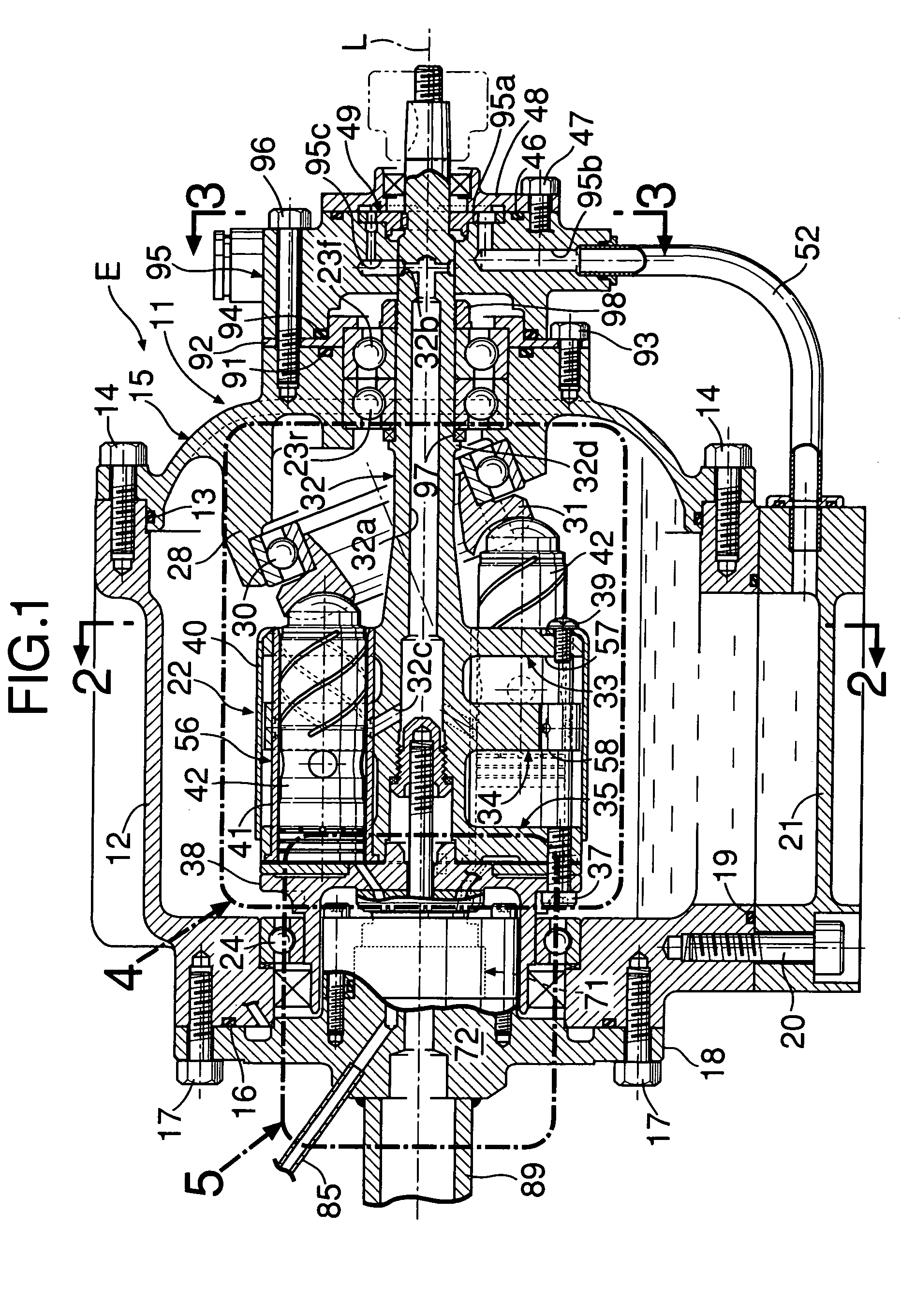
[0089]the present invention will be explained hereinafter based on FIG. 1 to FIG. 15.

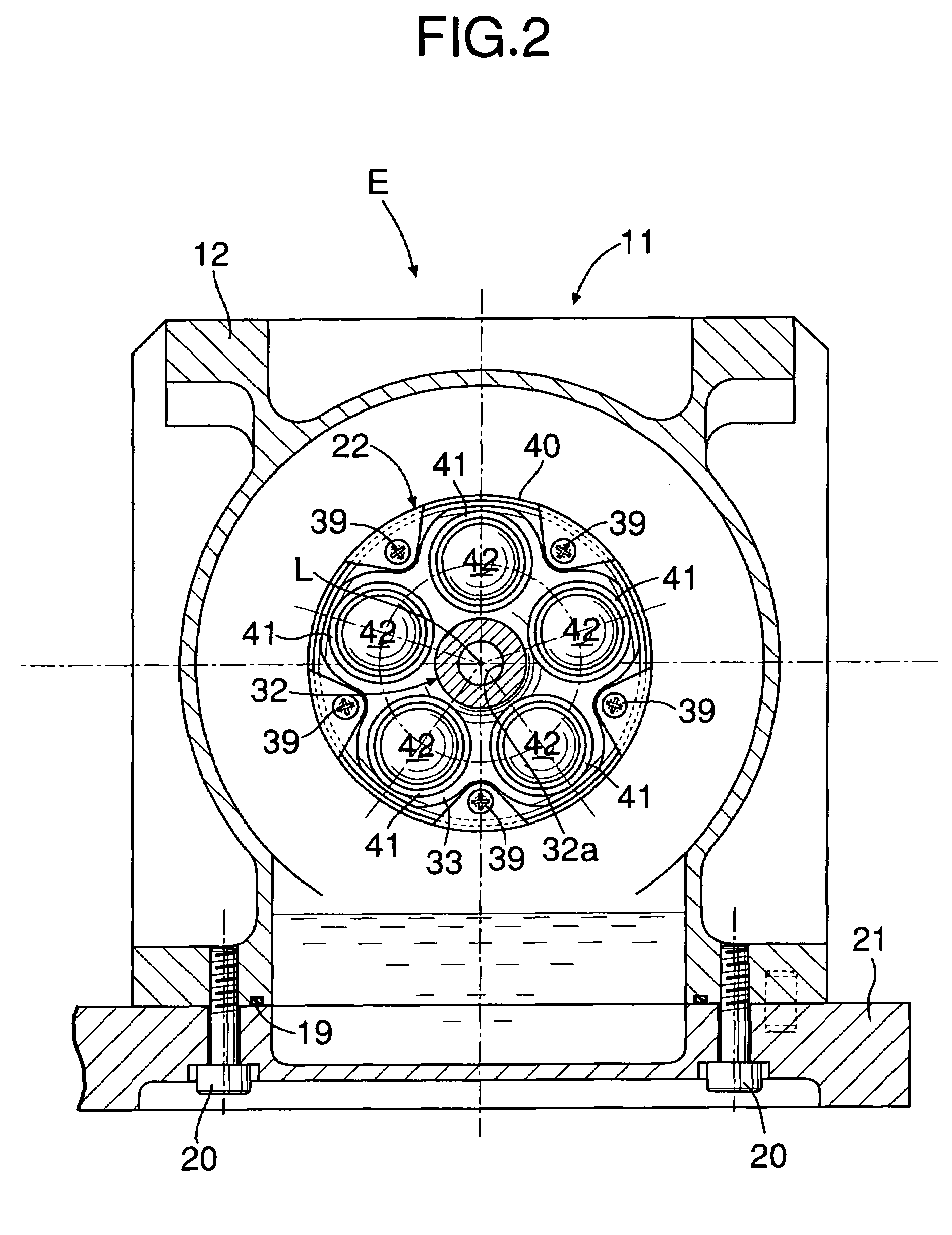
[0090]As shown in FIG. 1 to FIG. 9, an expansion machine E of this embodiment is used in, for example, a Rankine cycle apparatus, and converts thermal energy and pressure energy of high-temperature high-pressure steam as a working medium into mechanical energy and outputs it. A casing 11 of the expansion machine E is constructed by a casing body 12, a front cover 15 connected to a front surface opening of the casing body 12 with a plurality of bolts 14 . . . via a seal member 13, a rear cover 18 connected to a rear surface opening of the casing body 12 with a plurality of bolts 17 . . . via a seal member 16, and an oil pan 21 connected to a lower surface opening of the casing body 12 with a plurality of bolts 20 . . . via a seal member 19.

[0091]A rotor 22 rotatably disposed around an axis L extending in a longitudinal direction in a center of the casing 11 has its front portion supported by combinat...

second embodiment

[0149]Next, the present invention will be explained based on FIG. 16 to FIG. 19.

[0150]In the first embodiment, the steam discharge pipe 89 is disposed on the axis L of the rotor 22, and the steam supply pipe 85 is disposed to be eccentric to the outside in the radial direction, but in the second embodiment, the positional relationship is changed, and the steam supplying pipe 85 is disposed on the axis L of the rotor 22, while the steam discharge pipe 89 is disposed at the outer side in the radial direction.

[0151]The valve body portion 72 of the first embodiment is formed integrally with the rear cover 18, but the valve body portion 72 of the second embodiment is mounted to the rear cover 18 to be attachable and detachable. Namely, a circular flange 72a integrally formed at a rear portion of the valve body portion 72 abuts to the rear surface of the rear cover 18 via a seal member 101, and fixed thereto with a plurality of bolts 102. In this situation, a support portion 72b circular ...

third embodiment

[0161]Next, the present invention will be explained based on FIG. 20 and FIG. 21.

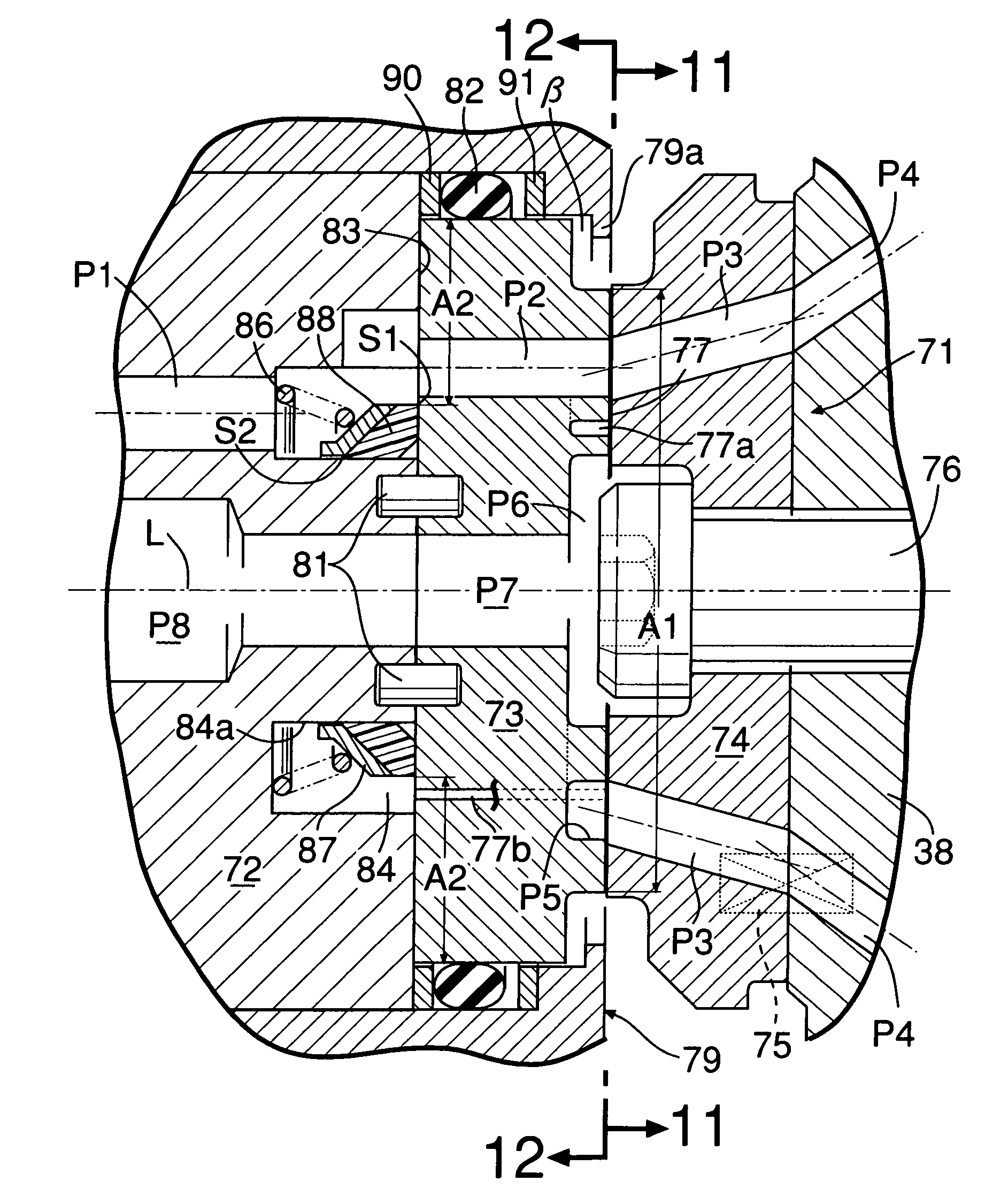
[0162]The third embodiment differs from the above-described second embodiment only in the structure of the inside of the pressure chamber 84, and therefore the different point will be mainly explained. In the second embodiment shown in FIG. 16, the first seal lip S1 of the V-packing 88 seals a space from the mating surface 83 of the fixed side valve plate 73, and the second seal lip S2 seals a space from the outer periphery surface of the steam supplying pipe 85. However, in the third embodiment, the first seal lip S1 of the V-packing 88 seals a space from the mating surface 83 of the fixed side valve plate 73, and the second seal lip S2 seals a space from an inner periphery surface 84a of the pressure chamber 84.

[0163]Namely, the packing retainer 87 which is biased by the coil spring 86 with the constant diameter without tapering includes a flat surface 87g to which the coil spring 86 abuts, a conical ...


PUM


Abstract

A rotary valve for switching supply passages, and discharge passages of high-temperature and high-pressure steam for a rotor rotatably supported at a casing is constructed by making a fixed side valve plate and a movable side valve plate abut to each other on a slide surface. A pressure chamber into which the high-temperature and high-pressure steam is introduced from the supply passage is opened to a mating surface of a valve body portion with the fixed side valve plate. The fixed side valve plate supported to float is pressed against the movable side valve plate with a pressing load generating in the pressure chamber to bring it into close contact with the slide surface. Leakage of the high-temperature and high-pressure steam from the pressure chamber is prevented by placing a V-packing inside the pressure chamber.

Description

[0001]This Nonprovisional application claims priority under 35 U.S.C. §119(a) on patent application No(s). 2003-061599; 2003-401320; 2003-401322 and 2003-401323 filed in JAPAN on Mar. 7, 2003; Dec. 1, 2003; Dec. 1, 2003 and Dec. 1, 2003, the entire contents of which are hereby incorporated by reference.BACKGROUND OF THE INVENTION[0002]1. Field of the Invention[0003]The present invention relates to a rotating fluid machine including a casing, a rotor rotatably supported at the casing, a working part provided at the rotor, and a rotary valve provided between the casing and the rotor to control supply and discharge of a working medium to and from the working part.[0004]2. Description of the Related Art[0005]Japanese Utility Model Laid-Open No. 61-155610 discloses a rotating fluid machine for supplying a combustion gas generating in a combustor to an axial piston cylinder group via a distributing mechanism (rotary valve), in which a pressing member is pressed with a spring to bring the ...

Claims


Application Information

Patent Timeline
Patent Type & Authority Patents(United States)
IPC IPC(8): F04B1/26F01B3/00F04B27/08
CPCF01B3/0032F04B27/0804F04B27/0839
Inventor MATSUMOTO, KENJIITOH, NAOKI
Owner HONDA MOTOR CO LTD
Why Eureka
Try Eureka