Vacuum freeze-drying apparatus and frozen particle manufacturing method

a vacuum freeze-drying and manufacturing method technology, applied in drying machines, lighting and heating apparatus, drying machines, etc., can solve the problems of air leakage and the decrease of vacuum freeze-drying performance, and achieve the improvement of sealing performance, sealing performance of the valve element and the valve seat inside the collection tank.

Active Publication Date: 2013-09-19
ULVAC INC
View PDF15 Cites 1 Cited by
  • Summary
  • Abstract
  • Description
  • Claims
  • Application Information

AI Technical Summary

Benefits of technology

[0018]The sealing performance of the valve element and the valve seat inside the collection tank can be improved. If the sealing performance is improved, the vacuum ambience inside the vacuum tank can be maintained, and the vacuum freeze-drying performance can be maintained. Furthermore, because the vacuum freeze-drying process can be carried out inside the vacuum tank while the frozen particles are carried out from the inside of the collection tank, the productivity is improved.

Problems solved by technology

Thus, there has been a problem in that leaks (air leaks) occur inside the vacuum tank 111 when the inside of the collection tank 112 is opened to the air atmosphere; and as a result, the vacuum freeze-drying performance is decreased.

Method used


Image

  • Vacuum freeze-drying apparatus and frozen particle manufacturing method
  • Vacuum freeze-drying apparatus and frozen particle manufacturing method
  • Vacuum freeze-drying apparatus and frozen particle manufacturing method

Examples


Embodiment Construction

[0025]The structure of the vacuum freeze-drying apparatus of the present invention will be explained below.

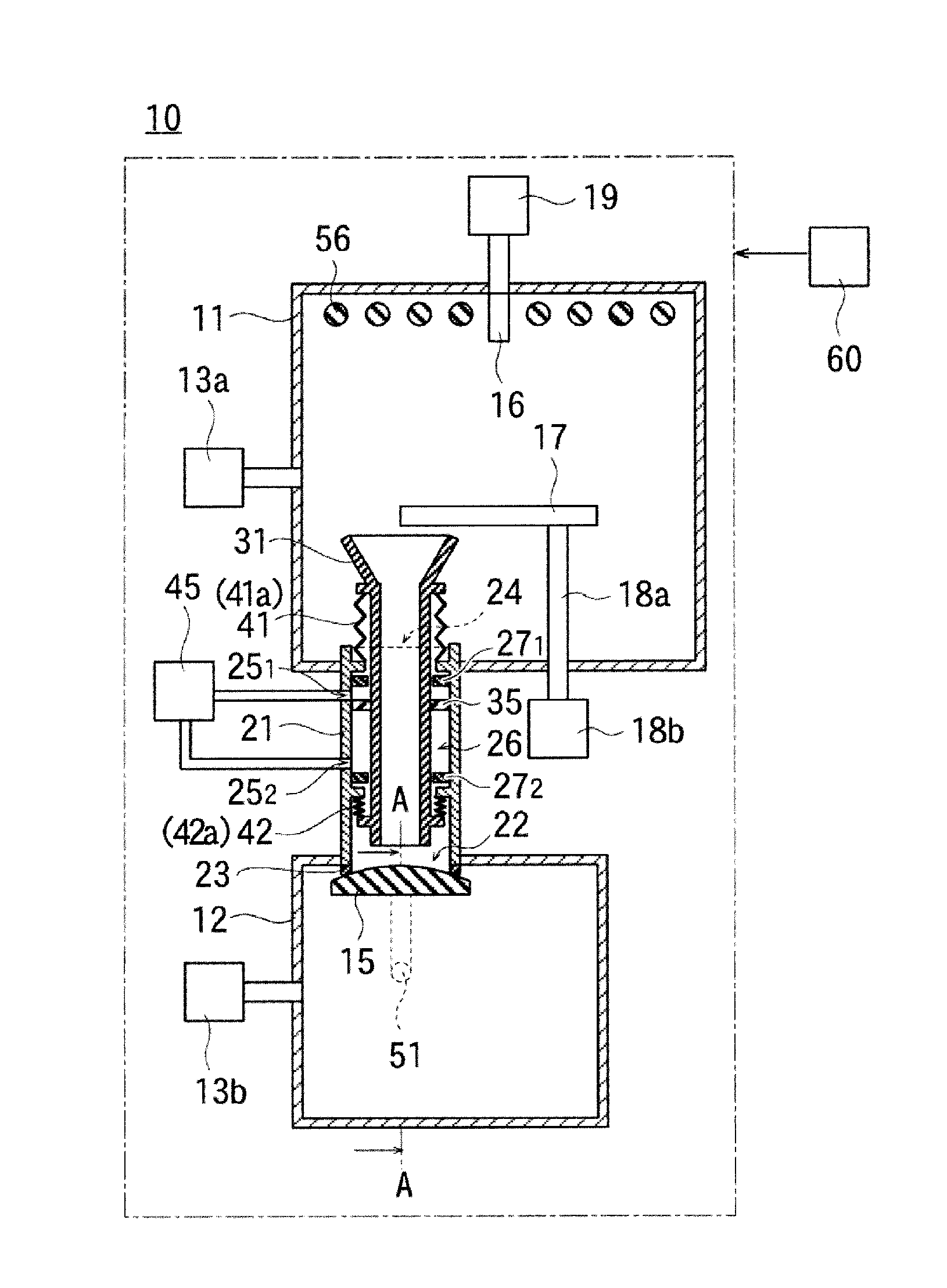
[0026]FIG. 1 shows the internal configuration of a vacuum freeze-drying apparatus 10.

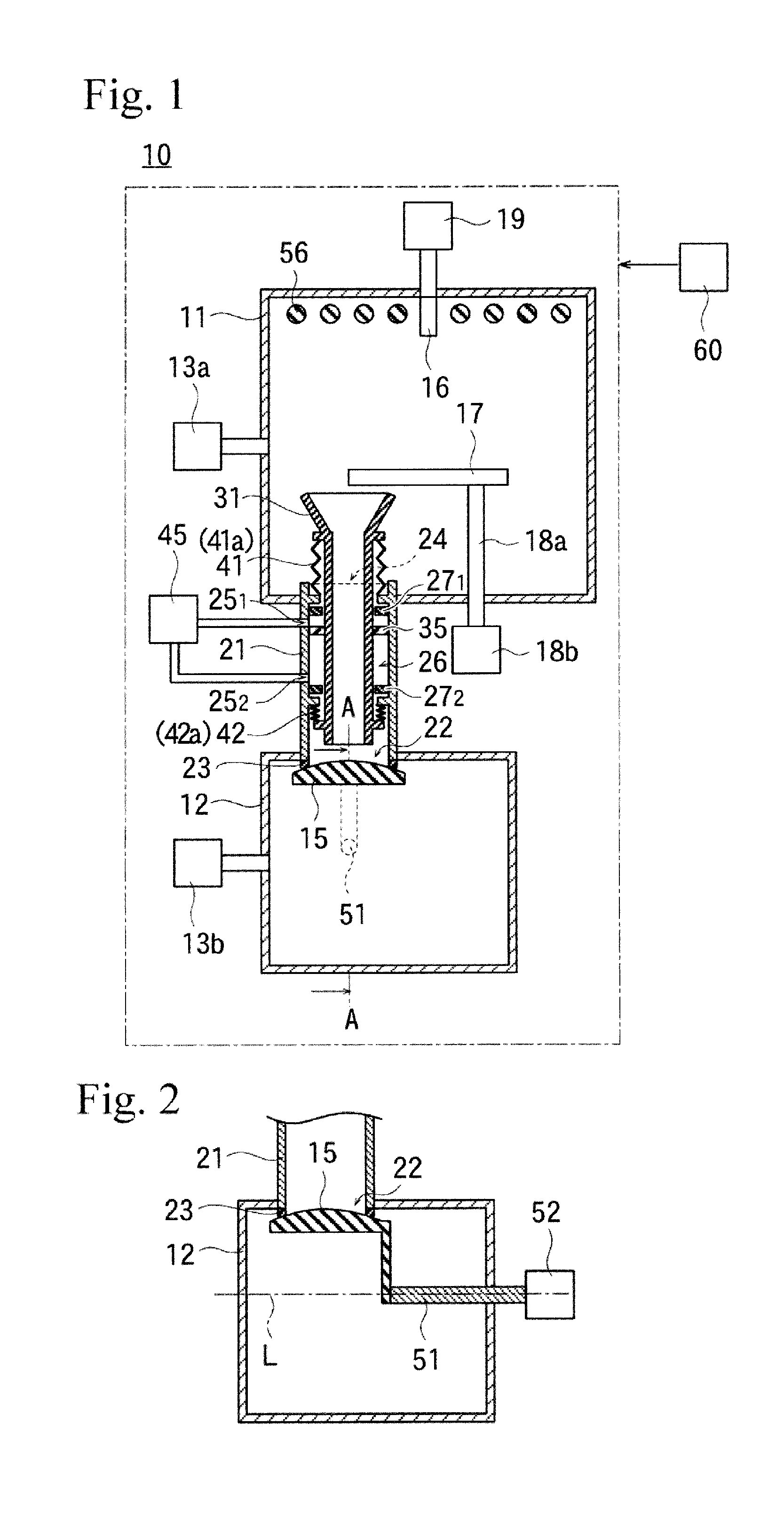
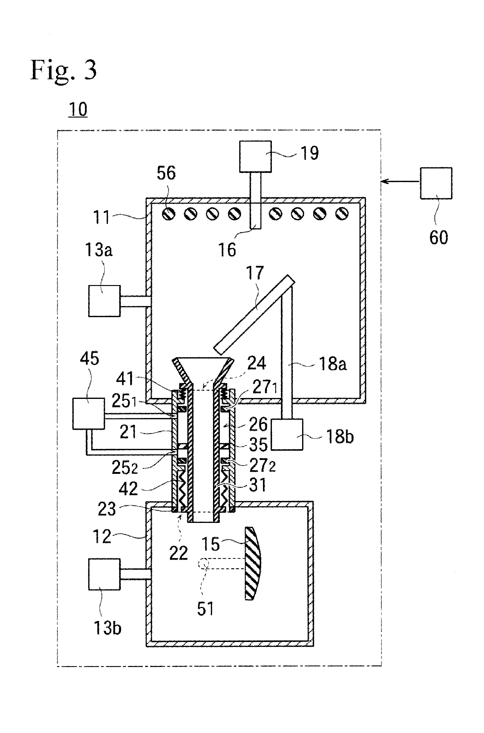
[0027]The vacuum freeze-drying apparatus 10 includes a vacuum tank 11, a collection tank 12 disposed below the vacuum tank 11, a main pipe 21 having a first opening 22 and a second opening 24 respectively at one end and the other end (i.e, the first opening 22 is provided at the one end, and the second opening 24 is provided at the other end) and the first opening 22 being exposed inside the collection tank 12 and the second opening 24 being exposed inside the vacuum tank 11, and a valve element 15 that switches between blocking and opening the first opening 22.

[0028]In the present embodiment, the main pipe 21 has a cylindrical shape, and a center axis line thereof is oriented parallel to the vertical direction. A top end of the main pipe 21, which is the one end, is inserted in an air tight fa...


PUM


Abstract

A technology for protecting a valve seat inside a collection tank from the adherence of frozen particles in a vacuum freeze-drying apparatus and a frozen particle manufacturing method. The inside of a vacuum tank and a collection tank are vacuum evacuated; a raw material liquid is injected into the vacuum tank to produce frozen particles; and the frozen particles are piled up on a surface of a heating/cooling shelf. When the frozen particles on the heating/cooling shelf are transferred into the collection tank through the inside of an auxiliary pipe, the frozen particles do not adhere to a valve seat which surrounds an opening of a main pipe inside the collection tank.

Description

BACKGROUND[0001]The present invention is generally related to a vacuum freeze-drying apparatus and a frozen particle manufacturing method.[0002]FIG. 6 is an internal configuration view of a conventional vacuum freeze-drying apparatus.[0003]A vacuum freeze-drying apparatus 100 includes a vacuum tank 111, a collection tank 112 disposed below the vacuum tank 111, a pipe 121 provided respectively with first and second openings 122 and 124 at one end and the other end, the first opening 122 being exposed inside the collection tank 112 and the second opening 124 being exposed inside the vacuum tank 111, and a valve element 115 that switches between blocking and opening the first opening 122.[0004]A valve seat 123 having ring-shape is adhered to and fixed onto the other end of the pipe 121 so as to surround the first opening 122. The valve seat 123 is, for example, a rubber O-ring.[0005]The valve element 115 is disposed below the valve seat 123. When the surface of the value element 115 is...

Claims


Application Information

Patent Timeline
Patent Type & Authority Applications(United States)
IPC IPC(8): F26B5/12
CPCB01D1/18B01J2/04A23L3/44F26B5/12F26B5/065F26B5/06
Inventor ITO, MASAKIOOHINATA, YOUICHIITO, KATSUHIKOHANAMOTO, TAKASHIKINOSHITA, TAKAO
Owner ULVAC INC
Why Eureka
Try Eureka