
Oil filter housing

a technology for oil filters and housings, which is applied in the direction of lubricant mounting/connection, separation processes, lubrication elements, etc., can solve the problems of reducing the service life of the filter, reducing the oil consumption, and the filter element cannot be taken out of the housing, so as to achieve convenient and simple assembly and operation of the oil filter, simple and reliable structure of the protruding structure, and simple manufacturing

Active Publication Date: 2009-06-09
BEIJING SZYN TECH
View PDF7 Cites 1 Cited by
  • Summary
  • Abstract
  • Description
  • Claims
  • Application Information

AI Technical Summary

Benefits of technology

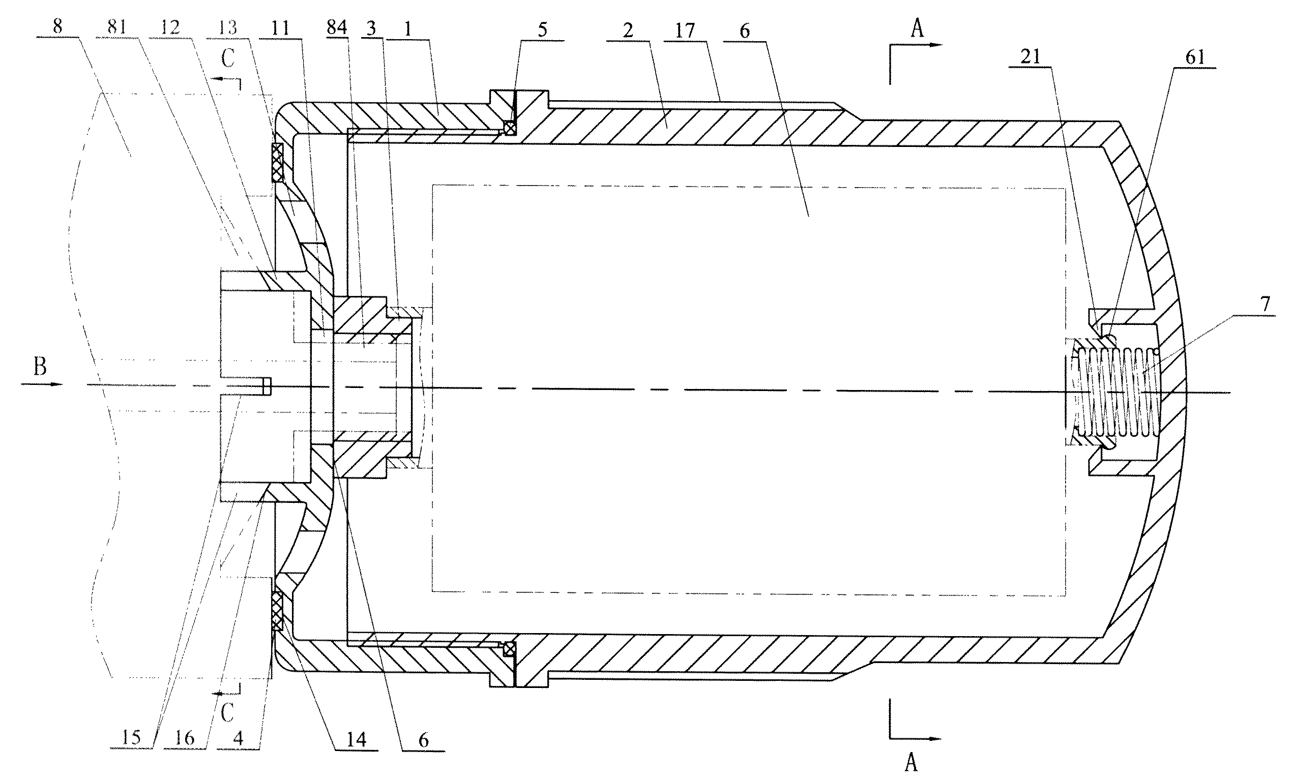
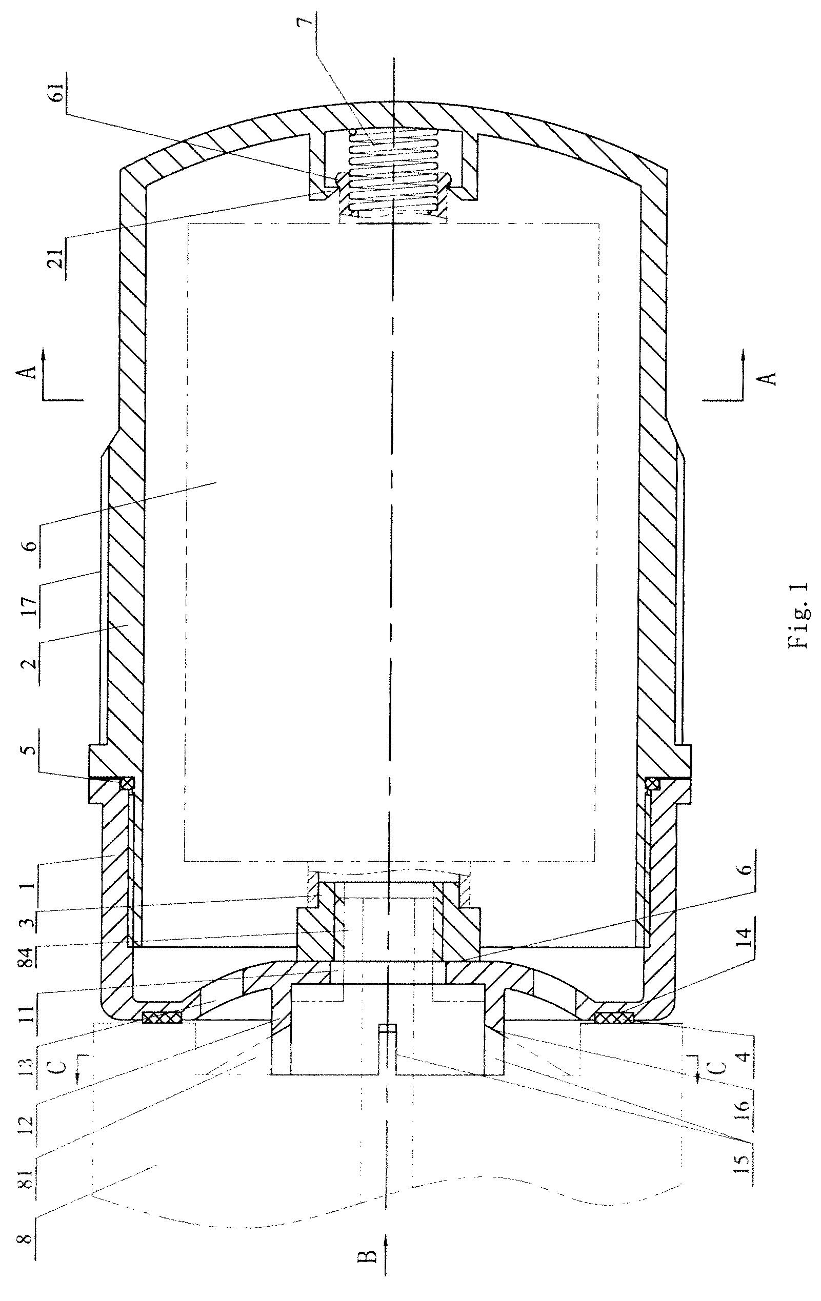
[0008]Accordingly, an embodiment of the present invention provides a separate oil filter housing which can be repeatedly used, detached conveniently, and easy to operate. Meanwhile, the sealing performance between the oil filter housing and a filter-mounting base is good.
[0028]According to an embodiment of the present invention, elastic hooks adapted to engage a filter element are provided on an inner bottom surface of the lower bowl. Using the elastic hooks engaging the filter element, the mounting and assembling of the filter element is convenient, and the operation is simple.

Problems solved by technology

Therefore, the oil filter has to be termly replaced frequently, otherwise the engine may suffer from abnormal abrasion which may result in power dropping of the engine, increasing of the oil consumption, and reduced operation life, even fuel leakage and detonation causing severe damage to or discard of the engine.
In addition, the filter element can not be taken out from the housing.
The housing and the filter element are discarded together after usage, thus resulting in waste.
In use, the housing may rotate relative to the engine body, which may resulting in oil leakage.
Thus, the replacement of the filter element can not be finished and operability thereof is poor.

Method used


Image

  • Oil filter housing
  • Oil filter housing
  • Oil filter housing

Examples


Embodiment Construction

[0037]Reference will be made in detail to embodiments of the present invention. The embodiments described herein with reference to drawings are explanatory, illustrative, and used to generally understand the present invention. The embodiments shall not be construed to limit the present invention. The same or similar elements and the elements having same or similar functions are denoted by like reference numerals throughout the descriptions.

[0038]The oil filter housing according to an embodiment of the present invention will be described with reference to the drawings.

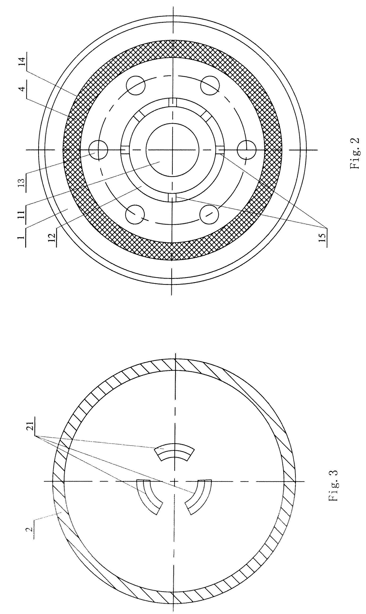
[0039]As shown in FIGS. 1 and 2, the oil filter housing according to an embodiment of the present invention comprises an upper bowl 1 and a lower bowl 2 which are detachably coupled to each other.

[0040]As shown in FIGS. 1 and 4, a bottom end of the upper bowl 1 (right end in FIG. 1) is open and a top end (left end in FIG. 1) surface is formed with oil inlets 13 and an oil outlet 11, the oil supplied from an oil pump (no...


PUM

PropertyMeasurementUnit
structureaaaaaaaaaa
temperatureaaaaaaaaaa
pressureaaaaaaaaaa

Abstract

The present invention discloses an oil filter housing, comprising an upper bowl adapted to be mounted onto a filter-mounting base of an engine, a top end of the upper bowl being formed with oil inlets and an oil outlet, and a protruding structure being provided on an outer top end surface of the upper bowl, the protruding structure adapted to be engaged with the filter-mounting base so as to position the upper bowl and limit rotation of the upper bowl relative to the filter-mounting base; and a lower bowl detachably coupled to the upper bowl and a bottom end of the lower bowl being closed. The oil filter housing according to an embodiment of the present invention is simple in structure, low in cost, easy to operation and safe.

Description

BACKGROUND OF THE PRESENT INVENTION[0001]1. Field of the Present Invention[0002]Embodiments of the present invention relate to an oil filter housing, more particularly to a separate oil filter housing.[0003]2. Description of the Related Art[0004]An oil filter is used to filter a medium, such as oil, lubricating an engine system. Impurities such as metal scraps, carbon particles produced and mixed into the oil during combustion and gum gradually produced by the oil are filtered by a filter element of the oil filter. Therefore, the oil filter has to be termly replaced frequently, otherwise the engine may suffer from abnormal abrasion which may result in power dropping of the engine, increasing of the oil consumption, and reduced operation life, even fuel leakage and detonation causing severe damage to or discard of the engine.[0005]Conventional oil filter housing of the oil filter has an integral steel-made body which is not detachable. In addition, the filter element can not be taken...

Claims


Application Information

Patent Timeline
Patent Type & Authority Patents(United States)
IPC IPC(8): B01D27/08B01D35/30
CPCB01D35/30F01M11/03
Inventor ZHU, MINGZHENCHEN, SHILIANG
Owner BEIJING SZYN TECH
Learn More