Multicarrier radio communication system, base station, radio relay station, mobile station, and multicarrier radio communication method

a radio communication system and multi-carrier technology, applied in the direction of digital transmission, transmission path division, transmission path sub-channel allocation, etc., can solve the problems of affecting the transmission of signals, so as to prevent interference

Inactive Publication Date: 2009-07-23
NTT DOCOMO INC
View PDF26 Cites 42 Cited by
  • Summary
  • Abstract
  • Description
  • Claims
  • Application Information

AI Technical Summary

Benefits of technology

[0029]Furthermore, the first subcarrier mapping means may allocate, to the signals retransmitted from the base station, subcarriers allocated by the radio relay station to the signals that are transmitted from the radio relay station and originated from signals previously transmitted from the base station. In this case, the base station and the radio relay station commonly use subcarriers for the signals, so that it is possible to prevent interference between the signals from the base station and the radio relay station.
[0030]In another embodiment, the first subcarrier mapping means may operate in a first allocation mode and a second allocation mode, the first subcarrier mapping means giving higher priority to signals destined for the second mobile station than signals destined for the first mobile station in connection with allocation of subcarriers in the first allocation mode, the first subcarrier mapping means giving higher priority to signals destined for the first mobile station than signals destined for the second mobile station in connection with allocation of subcarriers in the second allocation mode, the first subcarrier mapping means entering the second allocation mode from the first allocation mode once the signals destined for the first mobile station cannot be received successfully at the first mobile station, the first subcarrier mapping means entering the first allocation mode from the second allocation mode if a number of consecutive transmissions successfully received at the first mobile station exceeds a threshold. Accordingly, in an environment in which both of the radio link between the base station and the radio relay station and the radio link between the base station and the mobile station are affected by frequency selective fading, the first allocation mode can be ensured longer than the second allocation mode. In other words, the first subcarrier mapping means gives higher priority to the second mobile station MSNT for a longer time in subcarrier allocation. It is advantageous since reception at the second mobile station relies on only the radio relay station whereas the first mobile station can combine received signals from the base station and the radio relay station.

Problems solved by technology

Especially, the received signal power is significantly weak in NLOS (Non-Line-Of-Sight) propagation environment.
This makes difficult to ensure a large coverage area.
Loop interference may make difficult to relay signals correctly.
Those waves may result in frequency selective fading, which deteriorates quality of received signals.
However, in the resource allocation methods in radio relay system using multicarrier communication described in the above documents, it is not considered whether the mobile station to which resources are allocated can perform cooperative communication or not.
Accordingly, excessive resources may be allocated to a radio link to the mobile station which can improve reception characteristics by the cooperative diversity gain, so that the whole system may not have a sufficient capacity.

Method used


Image

  • Multicarrier radio communication system, base station, radio relay station, mobile station, and multicarrier radio communication method
  • Multicarrier radio communication system, base station, radio relay station, mobile station, and multicarrier radio communication method
  • Multicarrier radio communication system, base station, radio relay station, mobile station, and multicarrier radio communication method

Examples


first embodiment

Radio Communication System

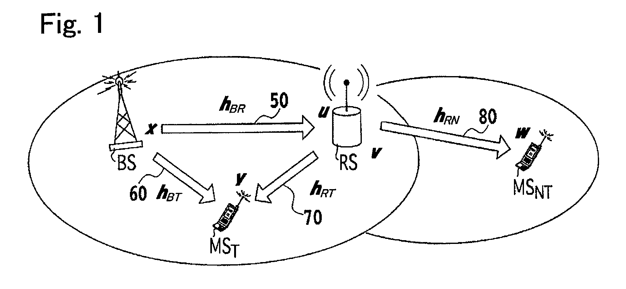
[0077]FIG. 1 is a view showing the overall structure of a multicarrier radio communication system (radio relay system), especially showing parts of the radio relay system which pertains to the present invention. In the embodiment, the present invention is applied to downlink communications.

[0078]As shown in FIG. 1, the radio relay system includes a base station (radio communication apparatus) BS, a radio relay station (radio relay apparatus) RS having a radio relay function. The radio relay system further includes a first mobile station MST (radio communication apparatus) located at a position where it is possible to directly communicate with the base station and to communicate with the radio relay station, so that the first mobile station MST can perform cooperative communication. The radio relay system further includes a second mobile station (radio communication apparatus) MSNT located at a position where it is impossible to directly communicate with the...

example of first embodiment

[0114]Next, with reference to FIGS. 6A through 9B, an example of a radio communication method in which radio resources are allocated in accordance with this embodiment will be described. This method is carried out in a radio relay system using OFDMA as the multicarrier communication scheme. In the example, each of the base station BS, the radio relay station RS, and the mobile stations has a single antenna in order to execute half-duplex relay in which reception and transmission at the relay station RS are conducted at different time slots.

[0115]In the following description, each parameter denoted in bold face is a vector form consisting of values at different frequencies (subcarriers), whereas each parameter denoted in small face is a scalar form having a value at a frequency (subcarrier).

[0116]FIG. 6A is a diagram showing a communication status at time slot [2i−1] where i is a natural number. As shown in FIG. 6A, the base station BS as the transmission source transmits to the radi...

second embodiment

[0151]A second embodiment of the present invention will be described below. In the following description, differences between the first and second embodiments will be elaborated.

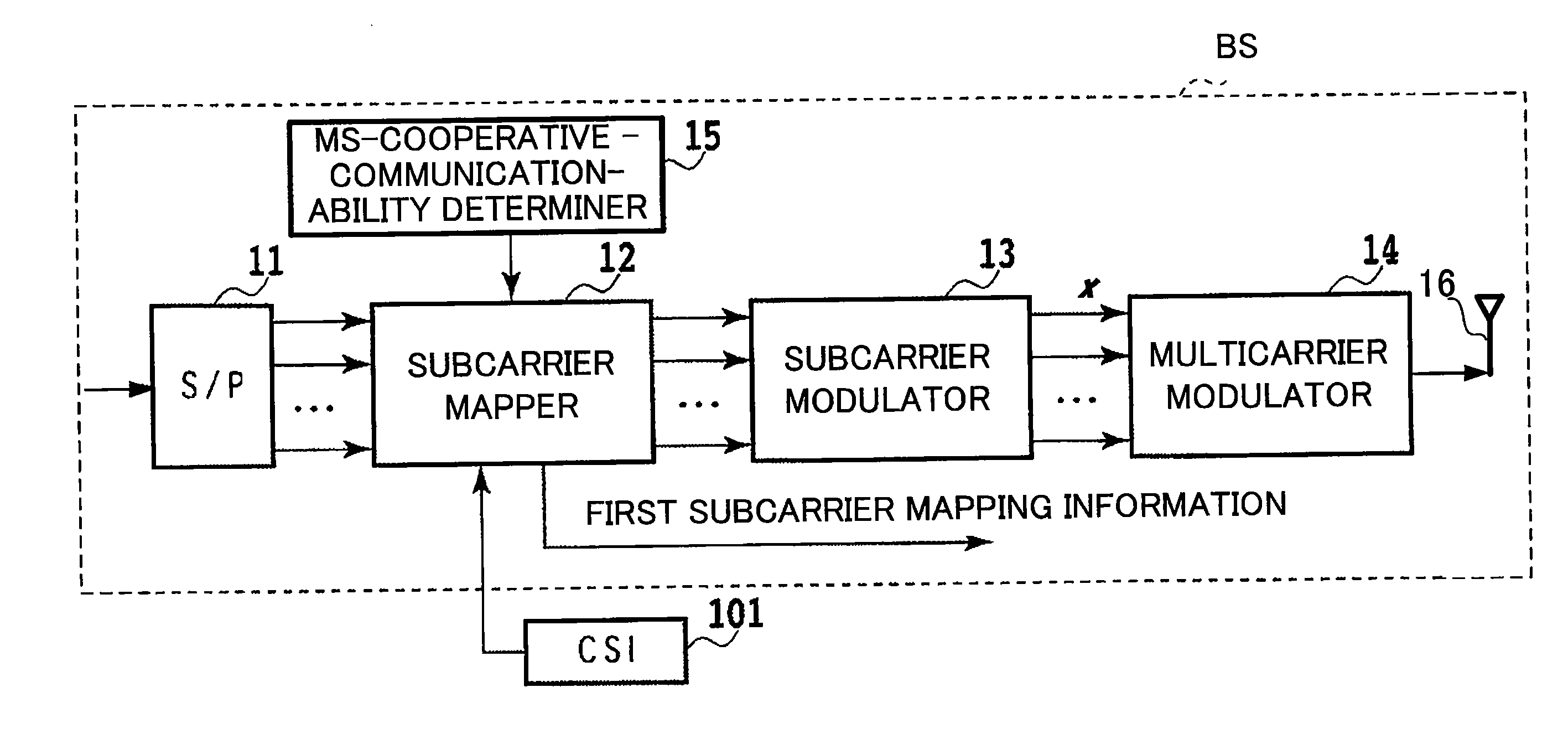
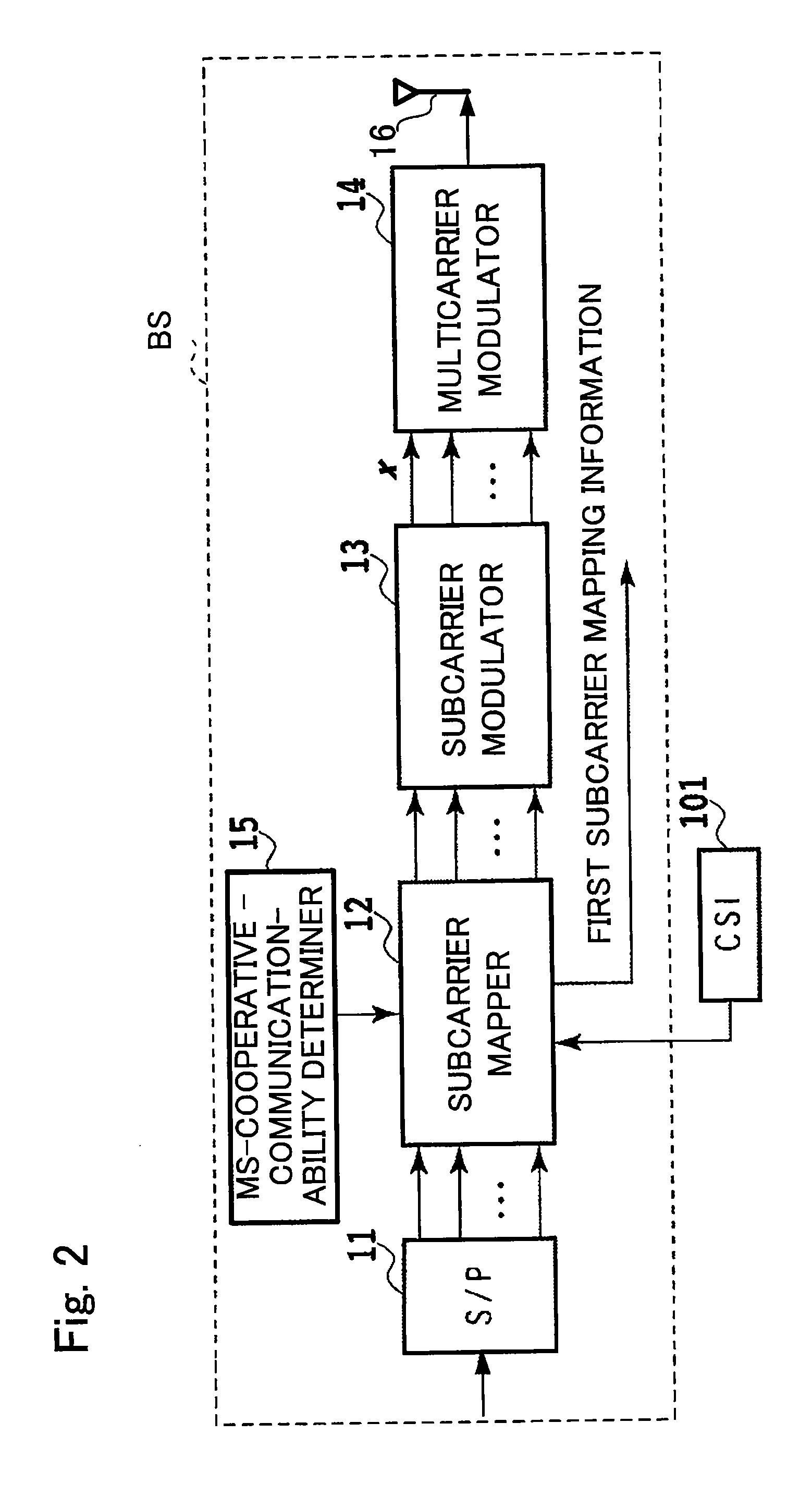
[0152]In the first embodiment, at time slot [2i] where i is a natural number, only the radio relay station RS sends downlink parallel signals v[2i]. In the second embodiment, at time slot [2i], the base station BS sends downlink parallel signals y[2i] of which the contents are the same as in the parallel signals y[2i−1] previously transmitted, and simultaneously, the radio relay station RS sends downlink parallel signals v[2i] of which the contents are the same as in the parallel signals y[2i−1] previously transmitted from the base station BS. This may further improve the cooperative diversity gain at the mobile station MST. For this purpose, the subcarrier mapper 12 resends to the subcarrier modulator 13 the parallel signals previously transmitted destined for the first mobile station MST. The subcarrier ma...


PUM


Abstract

A multicarrier radio communication system includes a first mobile station located at a position where it is possible to directly communicate with the base station and to communicate with a radio relay station, and a second mobile station located at a position where it is impossible to directly communicate with the base station and it is possible to communicate with the radio relay station. For allocating subcarriers to signals, the base station determines an order of priority for signals destined for mobile stations on the basis of whether each mobile station is the first mobile station or not. The radio relay station allocates subcarriers to the signals, independently of subcarrier allocation made at the base station. For allocating subcarriers, the radio relay station determines an order of priority for signals on the basis of whether each mobile station is the first mobile station or not.

Description

RELATED APPLICATIONS[0001]This application claims priority under 35 U.S.C. §119 to Japanese Patent Application No. JP2008-008543 filed on Jan. 17, 2008, the entire content of which is hereby incorporated by reference.BACKGROUND OF THE INVENTION[0002]1. Field of the Invention[0003]The present invention relates to allocation of resources in radio relay techniques, and more specifically, to a multicarrier radio communication system, a base station, a radio relay station, a mobile station, and a multicarrier radio communication method in the system.[0004]2. Description of the Related Art[0005]Wideband radio communication schemes have been studied for realizing a radio communication system in which data is transmitted at a higher rate. For wideband signal transmission, the greater the fractional bandwidth, the more preferable, where the fractional bandwidth is the bandwidth divided by its center frequency. Accordingly, it is practical to use a higher frequency band for wideband signal tr...

Claims


Application Information

Patent Timeline
Patent Type & Authority Applications(United States)
IPC IPC(8): H04B7/00H04B15/00
CPCH04L5/0007H04L5/003H04L5/0091H04L5/006H04L5/0037
Inventor JATURONG, SANGIAMWONGASAI, TAKAHIRO
Owner NTT DOCOMO INC
Why Eureka
Try Eureka