Method for optimization of a frequency spectrum

a frequency spectrum and optimization technology, applied in the field of frequency spectrum optimization, can solve the problems the picket-fence effect, and the inability to accurately represent the time domain signal of the components of the frequency spectrum, and achieve the effect of reducing the leakage effect and the picket-fence effect, and relatively accurate frequency spectrum

Inactive Publication Date: 2009-07-23
I-SHOU UNIVERSITY
View PDF1 Cites 8 Cited by
  • Summary
  • Abstract
  • Description
  • Claims
  • Application Information

AI Technical Summary

Benefits of technology

[0017]Therefore, the harmonic components of the optimized frequency spectrum correspond to the graduations calculated in step g), such that the leakage effect and the picket-fence effect are reduced, and the frequency spectrum is relatively accurate via the method according to this invention.

Problems solved by technology

However, when a harmonic frequency of the sampling signal is not a multiple of frequency resolution, there are a picket-fence effect associated with frequency distortion and a leakage effect associated with amplitude distortion when transforming the time domain sampling signal to a frequency domain signal using FFT.
Although leakage energy is eliminated in the frequency spectrum, components in the frequency spectrum cannot accurately represent the time domain signal.
While the zero complement method can reduce the picket-fence effect, the amplitude in the spectrum is decreased, such that this method cannot reduce the leakage effect.
Thus, characteristics of the frequency spectrum are different from those of the time domain signal, such that the frequency spectrum cannot represent actual parameters of the sampling signal.
However, this conventional method has unavoidable disadvantages.
First, there is a great difference between the common factor and an original graduation interval such that the method cannot be used in an actual practice.
However, there is an error in the harmonic frequencies obtained by calculation, such that the common factor based upon the harmonic frequencies is not an optimum graduation interval.

Method used


Image

  • Method for optimization of a frequency spectrum
  • Method for optimization of a frequency spectrum
  • Method for optimization of a frequency spectrum

Examples


Embodiment Construction

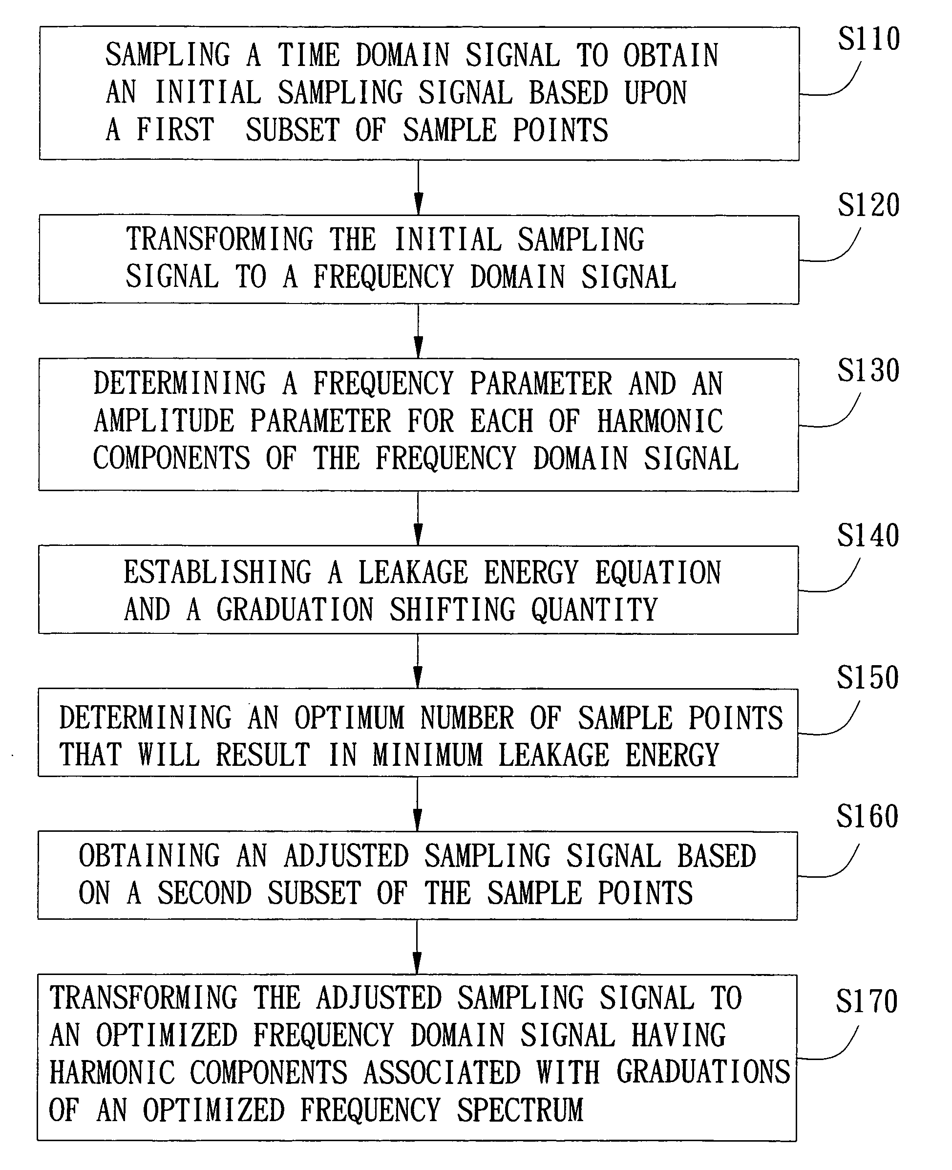
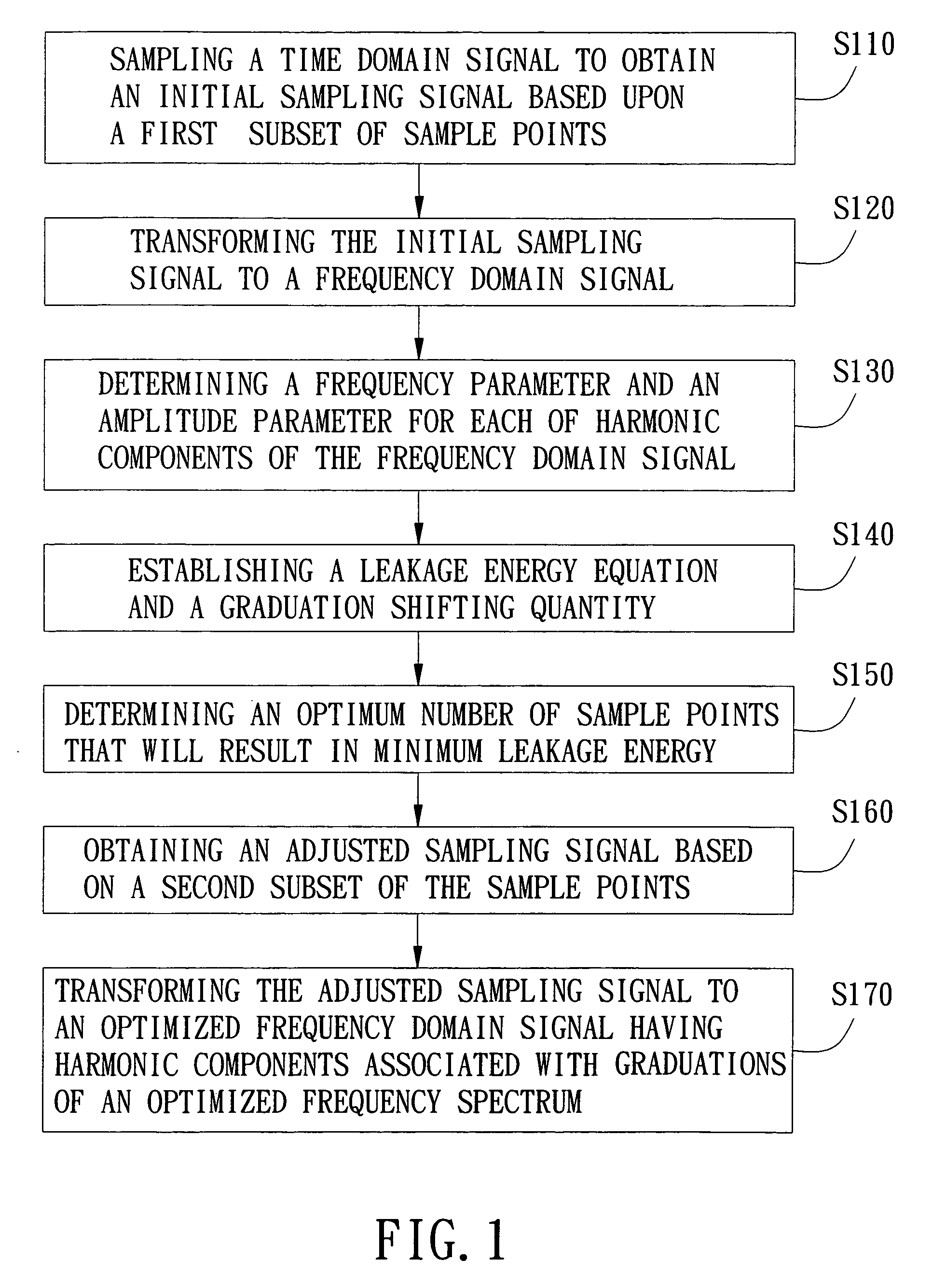
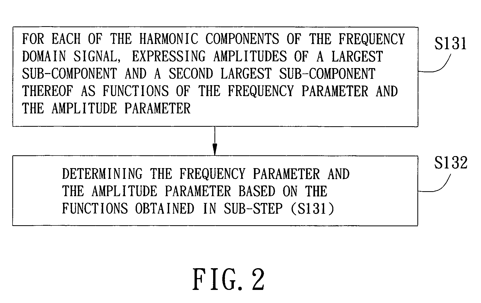
[0029]Referring to FIGS. 1 and 2, the preferred embodiment of a method for optimization of a frequency spectrum according to the present invention includes the following steps.

[0030]The first step (S110) is to sample a time domain signal at a number of sample points, followed by obtaining an initial sampling signal based on a first subset of the sample points. The time domain signal is sampled according to a predetermined sampling frequency and during a predetermined duration of sampling. The sampling frequency is more than twice the highest frequency of the time domain signal to conform with sampling principles. At least three identical waveforms are contained in the time domain signal during the duration of sampling when the time domain signal is a periodic signal, such that the initial sampling signal is able to present characteristics of the time domain signal.

[0031]The periodic time domain signal can be considered as a combination of a plurality of linear independent vectors, a...


PUM


Abstract

A method for optimization of a frequency spectrum includes the following steps: sampling a time domain signal to obtain an initial sampling signal based upon a first subset of sample points; transforming the initial sampling signal to a frequency domain signal; determining a frequency parameter and an amplitude parameter for each of harmonic components of the frequency domain signal; establishing a leakage energy equation and a graduation shifting quantity; determining an optimum number of sample points that will result in minimum leakage energy; obtaining an adjusted sampling signal based on a second subset of the sample points, wherein the number of the sample points in the second subset is equal to the optimum number; and transforming the adjusted sampling signal to an optimized frequency domain signal having harmonic components associated with graduations of an optimized frequency spectrum, wherein the graduations are calculated based upon the graduation shifting quantity.

Description

CROSS-REFERENCE TO RELATED APPLICATION[0001]This application claims priority to Taiwanese Application No. 097102035, filed Jan. 18, 2008, the disclosure of which is incorporated herein by reference.BACKGROUND OF THE INVENTION[0002]1. Field of the Invention[0003]The present invention relates to a method for optimization of a frequency spectrum, more particularly to a method for optimization of a frequency spectrum by shifting graduations of the frequency spectrum to reduce an error caused by a leakage effect.[0004]2. Description of the Related Art[0005]General commercial harmonic measuring devices, such as a spectrum analyzer, a harmonic analyzer, a distortion analyzer, digital harmonic measuring equipments, etc., utilize Fast Fourier Transform (FFT) to transform a time domain sampling signal to a frequency domain signal for spectrum analysis, although each of the harmonic measuring devices has a different function. However, when a harmonic frequency of the sampling signal is not a m...

Claims


Application Information

Patent Timeline
Patent Type & Authority Applications(United States)
IPC IPC(8): G01R23/16G06F19/00
CPCG01R23/16
Inventor WU, RONG-CHINGCHIANG, CHING-TAIWU, YUNG-CHUN
Owner I-SHOU UNIVERSITY
Why Eureka
Try Eureka