
Flow sensor and actuator

a flow sensor and actuator technology, applied in the direction of liquid transfer devices, service pipe systems, instruments, etc., can solve the problems of large quantity of water, add construction and maintenance costs, etc., and achieve the effect of remote testing economically and relatively easy to achiev

Active Publication Date: 2009-07-30
AGF MFG
View PDF4 Cites 11 Cited by
  • Summary
  • Abstract
  • Description
  • Claims
  • Application Information

AI Technical Summary

Benefits of technology

[0002]In a typical fire suppression water sprinkler system as installed in many buildings, an array of individual fire sprinklers is supplied with water through a main conduit and various branch conduits. The individual fire sprinklers are generally provided with a member that melts when the ambient temperature reaches a predetermined level indicative of a fire. The melting of the member opens a fire sprinkler to spray water in order to suppress the fire. The individual fire sprinklers are provided with meltable members so that the spray of water will hopefully be limited to the region of the building where the fire is present. In this way, the extent of water damage may be minimized.
[0008]The construction industry has increasingly recognized the environmental, economic and health and community benefits of providing so-called green buildings. The establishment of the leadership in energy and environmental design (LEED) Green Building Rating System™ recognizes that reducing water consumption provides environmental, economic and health and community benefits. These benefits include, for example, conserving natural resources, reducing operating costs, enhancing asset value and profits and minimizing the strain on local infrastructure.
[0010]A further object of the preferred embodiments of the present invention is to provide a testing arrangement by which a fire suppression system fluid flow sensor may be tested remotely economically and relatively easily.

Problems solved by technology

Although an individual test of a fire suppression fluid flow sensor may require 10 to 12 gallons, in a large multi-story building the testing procedure results in the use of a large quantity of water that is ultimately released into the waste water system.
The provision of testing valves for each conduit also adds construction and maintenance costs.

Method used


Image

  • Flow sensor and actuator
  • Flow sensor and actuator
  • Flow sensor and actuator

Examples


Embodiment Construction

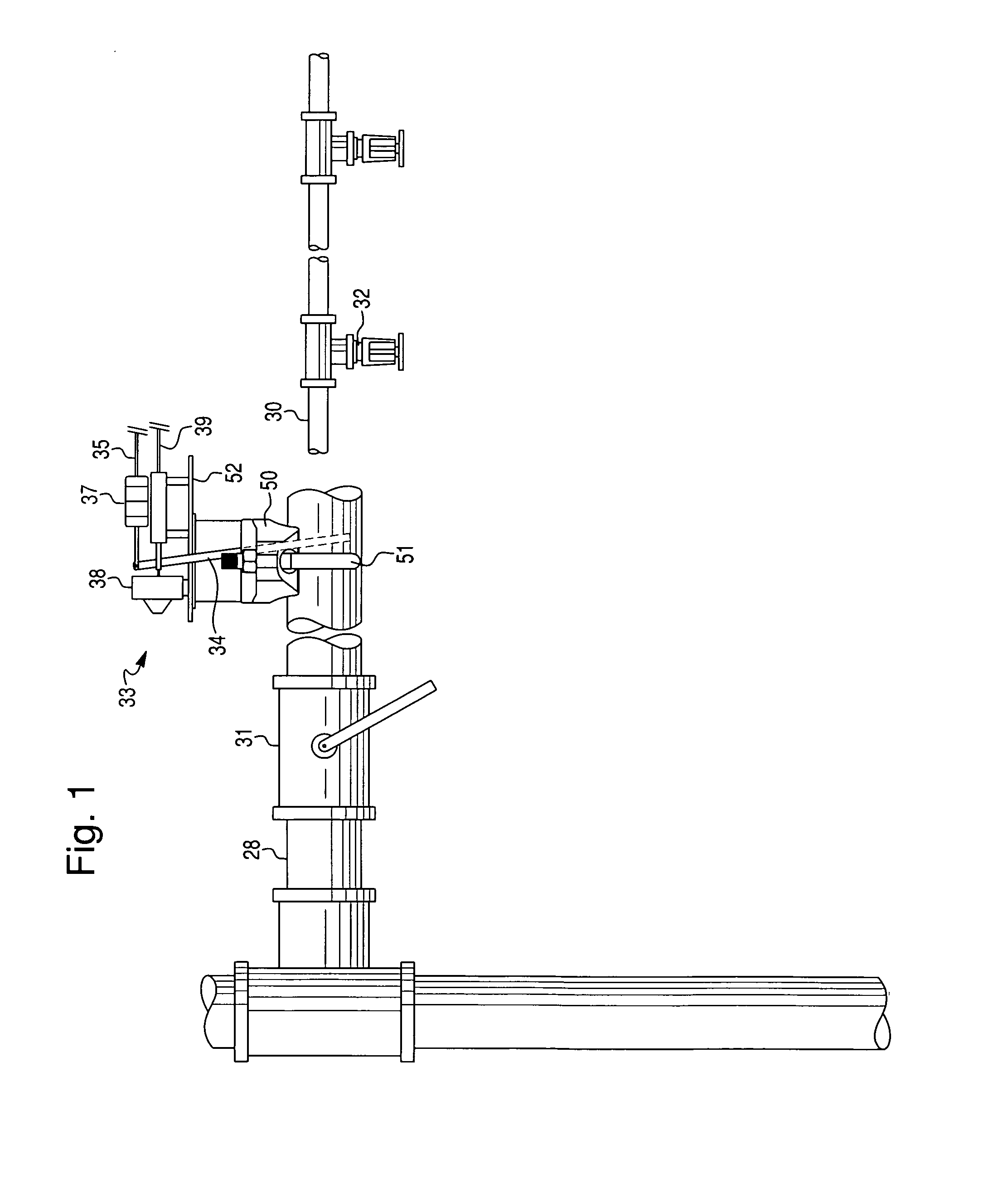
[0022]As shown in FIG. 1, a main conduit 28 for a fire suppression fluid such as water is provided in fluid communication with a plurality of branch conduits 30 including a number of sprinkler heads 32. Typically, a supply valve 31 either for the entire fire suppression system or for a particular floor or for a portion of the system, is provided in the main conduit 28. Downstream of the supply valve 31 is a flow sensor or switch 33 which is configured to detect a flow of fire suppression fluid through the main conduit 28 corresponding at least to the flow through a single sprinkler head 32.

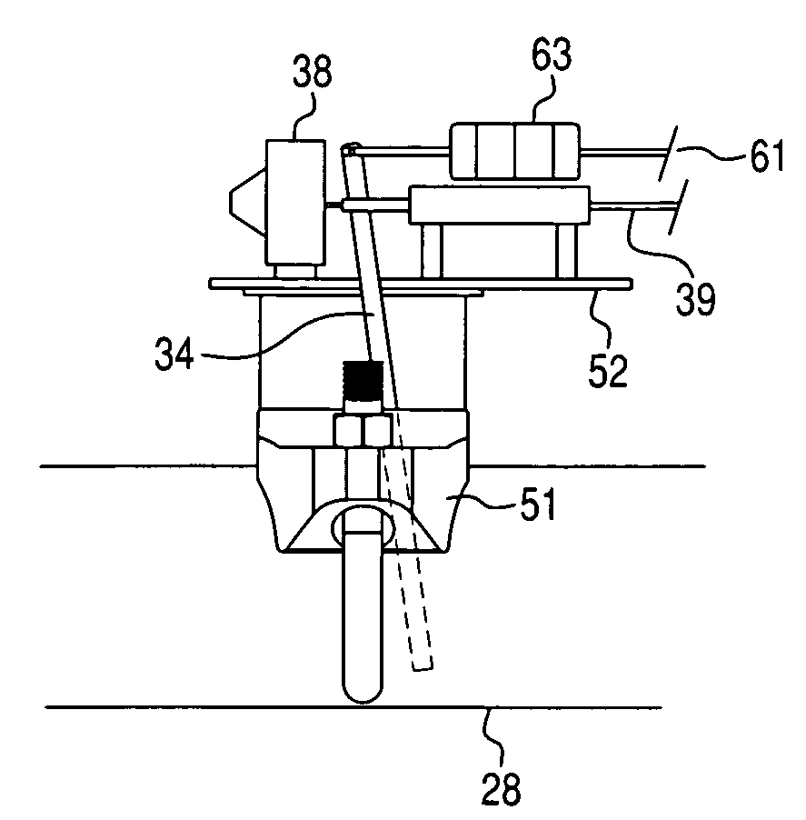
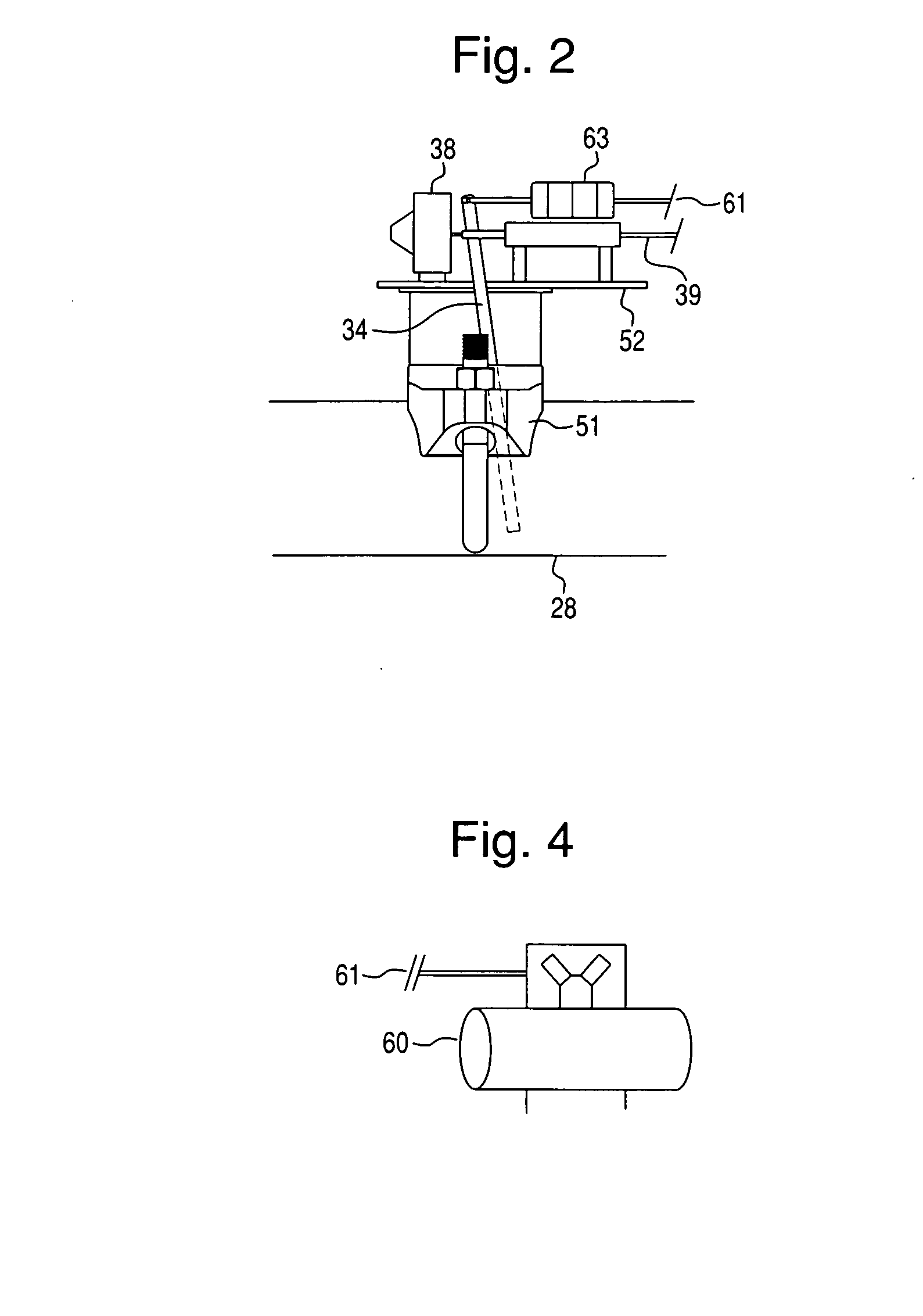
[0023]The flow sensor 33 detects the flow through the conduits to the sprinkler heads 32. This is accomplished by fluid flow pressure acting on a paddle 34 which is placed in the conduit. The flow of a fluid corresponding to at least the flow through a single sprinkler head 32 from left to right in FIG. 2, displaces the paddle 34 to the right as shown in FIG. 2, for example. In the absence of a fl...


PUM


Abstract

An arrangement for testing a fire suppression sprinkler system includes a conduit for supplying a flow of fire suppression fluid to at least one sprinkler. A sensor is configured to sense the flow of the fire suppression fluid to the at least one sprinkler. The sensor has a first condition indicative of a predetermined volume of flow of the suppression fluid to the at least one sprinkler and a second condition indicative of a volume of flow of the fire suppression fluid to the at least one sprinkler less than the predetermined volume of flow. An actuator causes the sensor to be in the first condition or the second condition. A signaler provides an indication to a user that the sensor is in at least one of the first condition and the second condition.

Description

BACKGROUND AND SUMMARY OF THE PRESENT INVENTION[0001]The present invention relates generally to testing fire suppression fluid sprinkler systems, and in particular relates to testing flow sensors or flow switches that detect the flow of fire suppression fluid in conduits.[0002]In a typical fire suppression water sprinkler system as installed in many buildings, an array of individual fire sprinklers is supplied with water through a main conduit and various branch conduits. The individual fire sprinklers are generally provided with a member that melts when the ambient temperature reaches a predetermined level indicative of a fire. The melting of the member opens a fire sprinkler to spray water in order to suppress the fire. The individual fire sprinklers are provided with meltable members so that the spray of water will hopefully be limited to the region of the building where the fire is present. In this way, the extent of water damage may be minimized.[0003]Such fire suppression syst...

Claims


Application Information

Patent Timeline
Patent Type & Authority Applications(United States)
IPC IPC(8): A62C37/08G01M19/00A62C37/50G01M99/00
CPCA62C37/50A62C35/58Y10T137/8326
Inventor MCHUGH, GEORGE J.
Owner AGF MFG
Learn More