Electric cable and insulator self-locking system, and method of installation thereof

a technology of self-locking and electric cables, which is applied in the direction of machine supports, garments, household objects, etc., can solve the problem of the insulator being unable to self-lock, and the clamp could accidentally detach from the insulator, so as to achieve the effect of safe and convenient us

Inactive Publication Date: 2009-07-30
BMC INNOVATIONS
View PDF4 Cites 11 Cited by
  • Summary
  • Abstract
  • Description
  • Claims
  • Application Information

AI Technical Summary

Benefits of technology

[0028]The present self-locking connector and biasing tool system will be effective for all types of ceramic insulator currently in use worldwide, and for most envisioned new plastic type insulators currently being developed. This self-locking system will be particularly well suited to replace the va

Problems solved by technology

The latter is attached to the insulator by the difficult operation of manually winding and twisting a small diameter tie wire around the electrical transmission cable and a waist portion at the base of

Method used


Image

  • Electric cable and insulator self-locking system, and method of installation thereof
  • Electric cable and insulator self-locking system, and method of installation thereof
  • Electric cable and insulator self-locking system, and method of installation thereof

Examples


Embodiment Construction

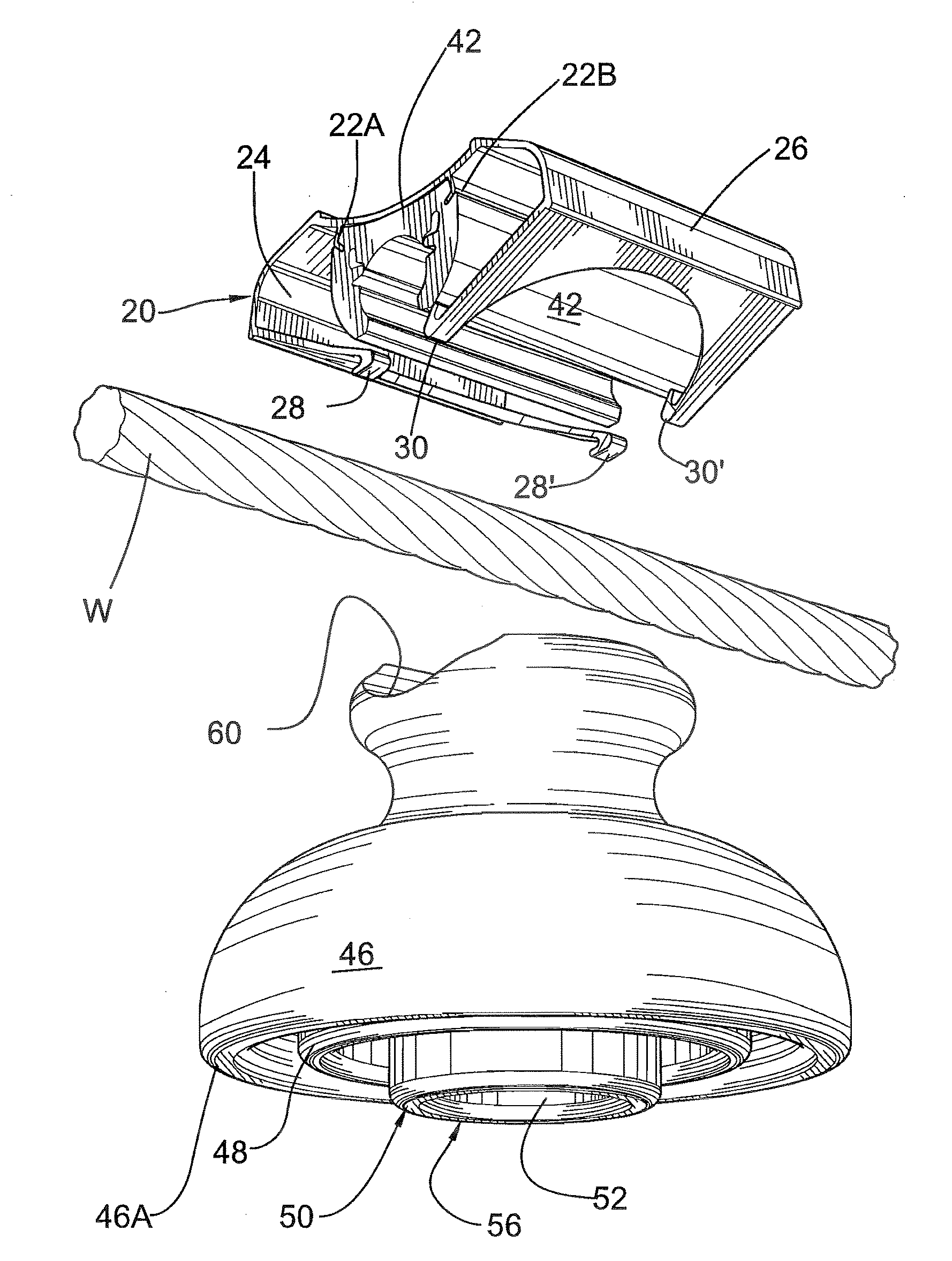
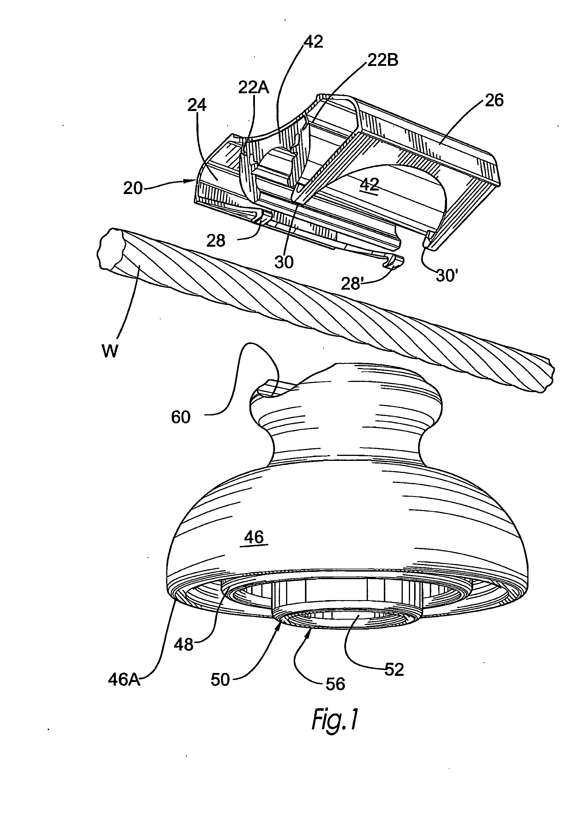
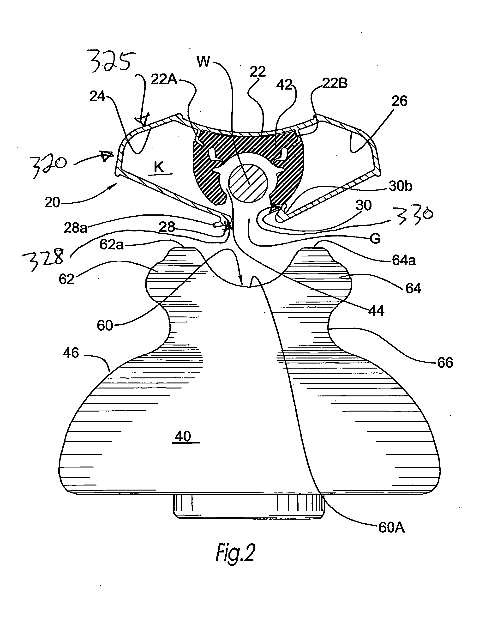
[0042]According to a first embodiment of the self-locking connector system illustrated in FIGS. 1-11, there is disclosed a semi-rigid clasp 20 having a main web 22 from which project a pair of opposite arcuate arms 24, 26. At least clasp main web 22, and preferably also side arms 24, 26, are made from a resilient material so as to be spring loaded wherein side arms 24 and 26 have limited tilt capability relative to one another. Each arm 24, 26, defines a main body with a pair of inner free end flange 28, 28′, and 30, 30′, respectively.

[0043]In their unbiased condition, the two side arms 24, 26, are spaced apart, and define a spacer gap G between their pairs of proximal end flanges 28, 28′, 30, 30′, wherein a generally open inner pocket K is circumscribed by web 22 and arms 24 and 26. Flanges 28, 28′, are in spaced register with flanges 30, 30′, when web 22 is unbiased. Laterally spaced flanges 28, 28′, of arm 24 are outturned, while laterally spaced flanges 30, 30′ of arm 26 are int...


PUM

PropertyMeasurementUnit
Resilienceaaaaaaaaaa

Abstract

The insulator comprises a lower bell shaped portion, an intermediate annular waist portion and an upper saddle portion for receiving and supporting an electric transmission overhead cable. An axial blind bore opens at its lower end for receiving an upstanding support pin. The saddle portion includes a transversely-curved groove, substantially normal to the axial bore, and jutting parts on each side of the cable receiving groove and laterally protruding from the waist portion. Each jutting part has an external face which is provide with a partly annular groove, generally coaxial with the bore and of greater radius than that of the waist portion. These annular grooves are adapted to positively retain the inturned flanges of a cable retaining clasp despite an upward force or a laterally upwardly directed force exerted by the cable on the clasp. The waist portion can still be used for attaching the electric wire by a tie-wire. The clasp includes male/female joints at each of its two downwardly curved arms that automatically interlock with each other when a sufficient biasing force is applied thereon by a pneumatic tool deforming the clasp arms, drawing the registering flanges of the latter toward one another to lock the insulator to the overhead electric cable.

Description

FIELD OF THE INVENTION[0001]The present invention relates to a self-locking connector and biasing tool system for the releasable quick connection to a rigid insulator of an airborne suspended electrical cable forming part of an airborne suspended electrical cable distribution network.BACKGROUND OF THE INVENTION[0002]Overhead electric cables are usually carried by porcelain insulator which are maintained upright by an upstanding pin engaging an axial blind bore of the insulator body, the pin fixed to the cross-arm of a ground pole or tower. The insulator has a saddle like upper portion which receives and supports the electrical cable. The latter is attached to the insulator by the difficult operation of manually winding and twisting a small diameter tie wire around the electrical transmission cable and a waist portion at the base of the insulator saddle portion.[0003]In international patent application publication NO WO 91 / 03061 dated 7 Mar. 1991 for an “insulator for overhead electr...

Claims


Application Information

Patent Timeline
IPC IPC(8): H01B17/22B23P17/00
CPCH01B17/10Y10T24/44017Y10T24/44598Y10T29/49947
Inventor CLOUTIER, FRANCOISGENTES, PAUL
Owner BMC INNOVATIONS
Why Eureka
Try Eureka