
Vehicle alternator provided with brushes and slip rings

a technology of vehicle alternator and slip ring, which is applied in the direction of current collector, dynamo-electric machines, basic electric elements, etc., can solve the problems of reducing the temperature of brushes and long brush life, and achieve the effect of improving the mechanical environment of vehicle alternator and significantly increasing the life of brushes

Active Publication Date: 2009-07-30
DENSO CORP
View PDF10 Cites 25 Cited by
  • Summary
  • Abstract
  • Description
  • Claims
  • Application Information

AI Technical Summary

Benefits of technology

[0008]The present invention has been invented in such a view, and it is therefore an object of the present invention to provide a vehicle alternator with increased amount of air for cooling a pair of brushes and for exhausting powders produced by sliding motion of the brushes. It is another object of the present invention to increase the lifetime of the pair of brushes and to improve the performance in exhausting the powder produced by sliding motion of the brushes, by individually providing a sufficient amount of air to each of the brushes.
[0010]Accordingly, the vehicle alternator is allowed to have a larger air passage compared to the conventional small gap formed between the brush and the first chamber, which can significantly increase the amount of air for cooling the sliding portions of the brushes and for removing the powder produced by sliding motion of the brushes. Further, the vehicle alternator allows the brush leads, which are electrically connected to the brushes, to be directly cooled, which prevents the temperature increase of both the brushes and the connection terminals. The prevention of the temperature increase of the connection terminals is able to prevent temperature increase of the brush holder to which the connection terminals are fixed. Consequently, such a construction can significantly decrease the temperature of the brushes, resulting in a long brush lifetime.
[0012]Further preferably, one of the first chambers is prepared for a positive electrode, and the other of the first chambers is prepared for a negative electrode; and one of the second chambers is prepared for the positive electrode, and the other of the second chambers is prepared for the negative electrode. Accordingly, the alternator is allowed to have a sufficient amount of air for cooling the brush at the front side as well as for the brush at the rear side, which can increase the lifetime of both brushes.
[0013]It is preferred that the first air holes have opening areas which are different from each other. Accordingly, the alternator can supply sufficient air to both the brush at the front side and the brush at the rear side, individually, based on the temperature difference between them caused by the positions of the brushes, by adjusting the opening area of each of the first air holes. This enables the lifetime of the brushes to be increased.
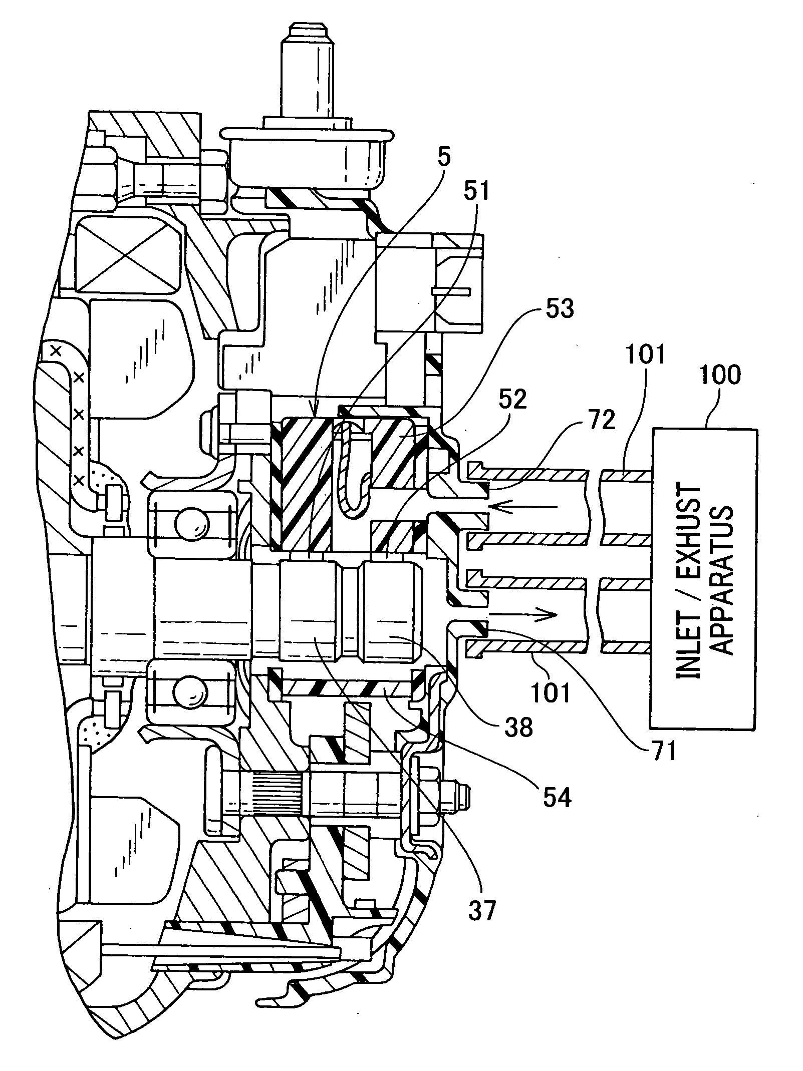
[0015]Accordingly, this construction having a simple structure allows air to be inlet and exhausted from / to the outside, which permits the lifetime of the brushes to be significantly increased, and the powder produced by sliding motion of the brushes to be sufficiently exhausted.
[0016]It is further preferred that the cylinder is connected to an inlet / exhaust apparatus disposed in the vehicle side via a connecting member. Accordingly, the inlet / exhaust apparatus is allowed to perform sufficient inletting and exhausting of the air, as well as the exhausting of powder produced by sliding motion of the brushes, which prevents the invasion of foreign objects and improves the mechanical environment of the vehicle alternator, even if the vehicle alternator operates under the over flooding condition.

Problems solved by technology

Consequently, such a construction can significantly decrease the temperature of the brushes, resulting in a long brush lifetime.

Method used


Image

  • Vehicle alternator provided with brushes and slip rings
  • Vehicle alternator provided with brushes and slip rings
  • Vehicle alternator provided with brushes and slip rings

Examples


Embodiment Construction

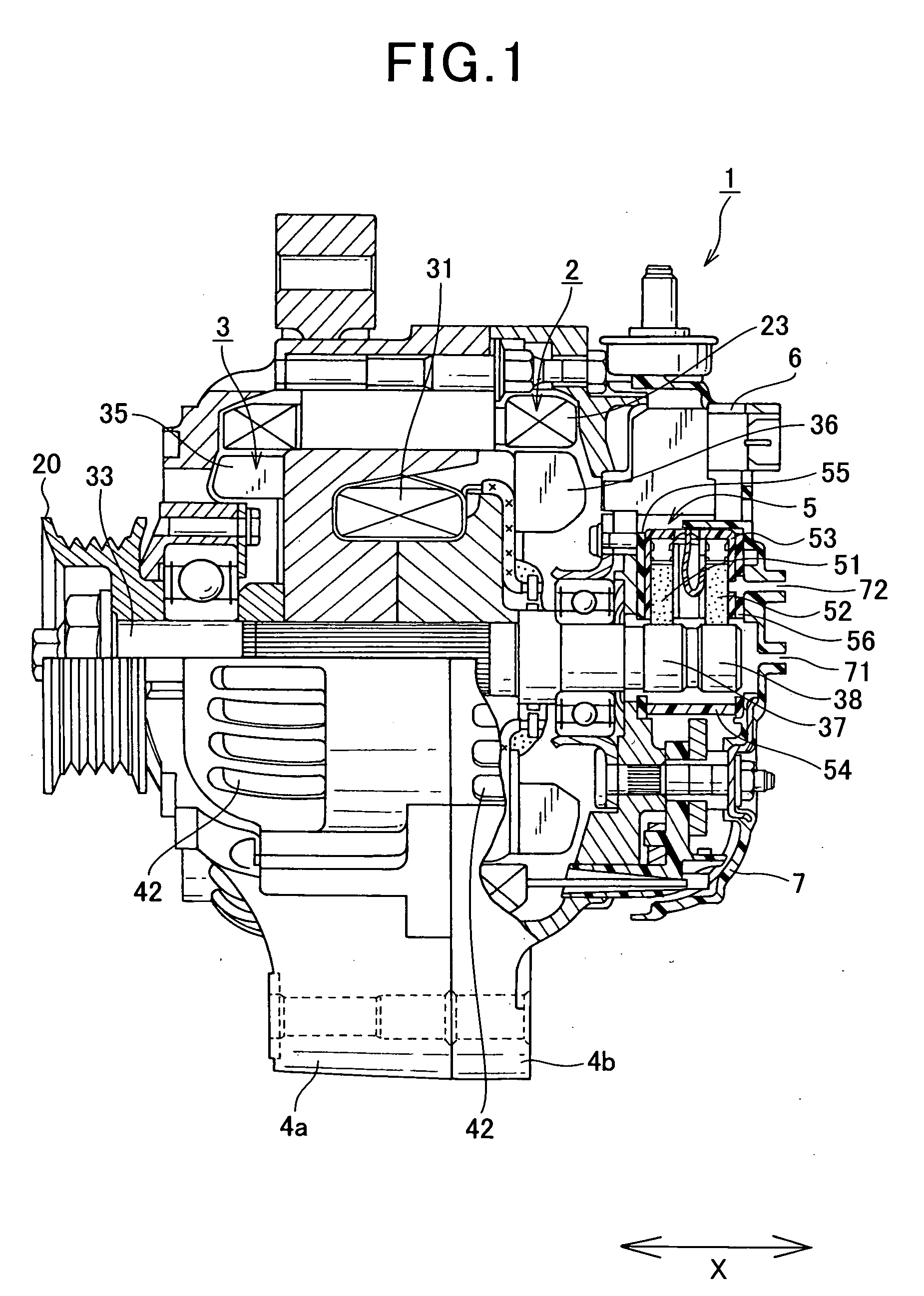
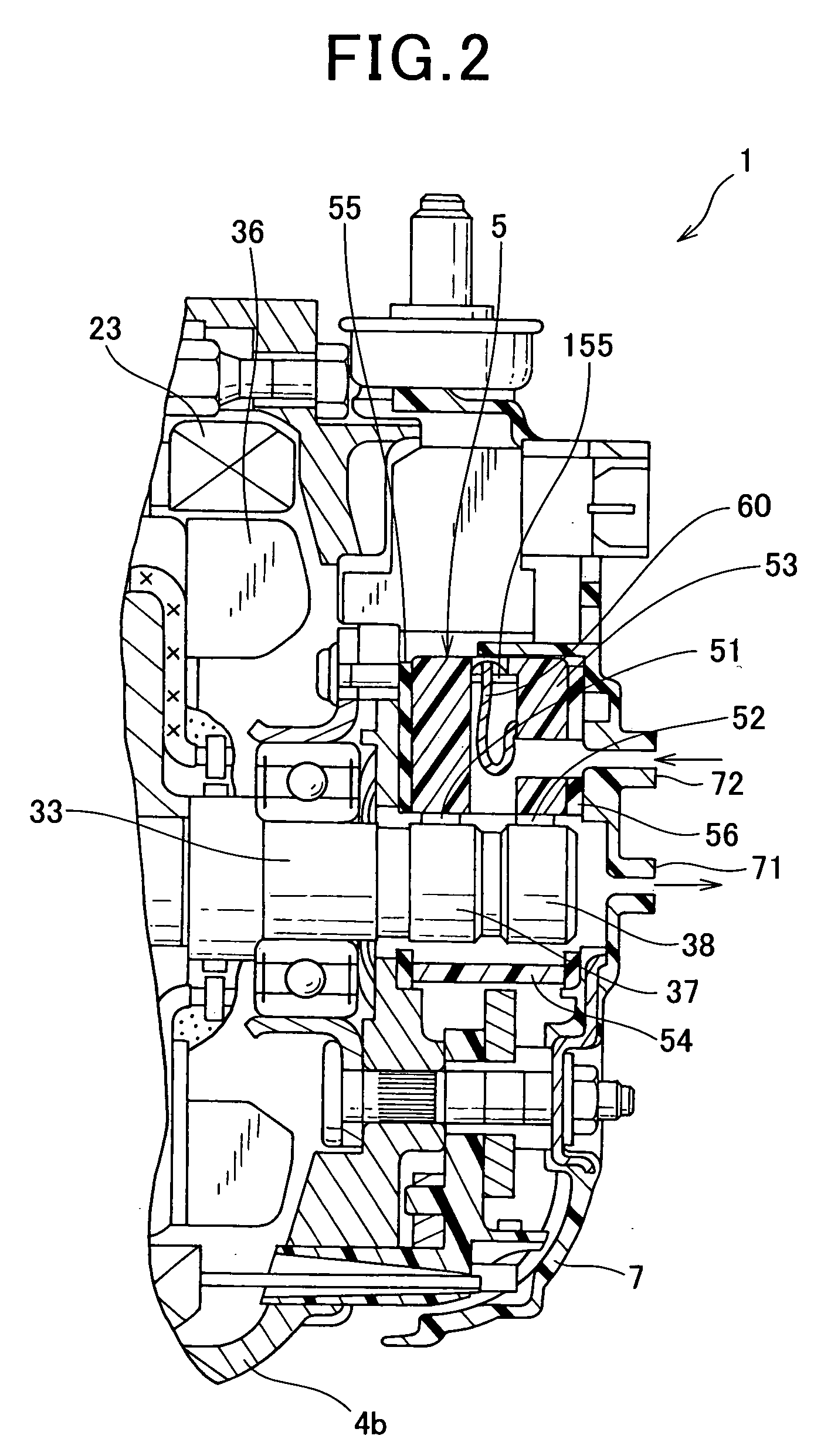
[0029]A vehicle alternator according to a preferred embodiment of the present invention will be described in detail referring to the drawings. FIG. 1 is a sectional view of the vehicle alternator according to the embodiment. FIG. 2 is an enlarged sectional view showing a substantial part of the vehicle alternator of the embodiment.

[0030]As illustrated in FIG. 1, the vehicle alternator 1 of the preferred embodiment comprises a stator 2 composed of a wire wound armature 23. The vehicle alternator 1 also comprises a rotor 3, which is composed of a field winding 31, and which is disposed against the inner circumference side of the stator 2. The vehicle alternator 1 further comprises cooling fans 35, 36, which are fixed to axial end faces of the rotor 3, and which function as a means for generating cooling air as the rotor 3 rotates. The vehicle alternator 1 also comprises a front-side housing 4a and a rear-side housing 4b that support the stator 2 and the rotor 3, a brush apparatus 5 fo...


PUM


Abstract

An alternator for vehicles, the alternator being provided with a rotary shaft, comprising slip rings fixed to a rotary shaft to be rotated with the rotary shaft, brushes being placed to be in slide contact with the slip rings a brush holder that accommodates the brushes to be held therein; connection terminals fixed to the brush holder, brush leads electrically connecting the brushes to the connection terminals respectively, and a slip ring cover that covers the slip rings in cooperation with the brush holder, wherein the brush holder comprises first chambers in which the bushes are fixedly accommodated second chambers in which the brush leads are accommodated, the second combers communicating with the first chambers, and first air holes formed to open outside of the housing and formed as inlet / exhaust passages communicating with the second chambers.

Description

CROSS REFERENCES TO RELATED APPLICATION[0001]The present application relates to and incorporates by reference Japanese Patent application No. 2008-016087 filed on Jan. 28, 2008.BACKGROUND OF THE INVENTION[0002]1. Field of the Invention[0003]The present invention relates to a vehicle alternator (i.e., AC generator) mounted to vehicles such as automobiles and trucks.[0004]2. Description of the Related Art[0005]A typical vehicle alternator widely known comprises a stator, and a rotor that is disposed against the inner surface side of the stator, both of which are accommodated in a housing. The rotor is fixedly provided with a cooling fan that generates cooling air as the rotor rotates about a rotary shaft. The cooling air generated by the cooling fan is exhausted through an exhaust window provided to the housing. The rotary shaft is fixedly provided with slip rings that rotate with the rotary shaft. The vehicle alternator further comprises components such as a brush holder for accommod...

Claims


Application Information

Patent Timeline
Patent Type & Authority Applications(United States)
IPC IPC(8): H02K9/28
CPCH02K9/28
Inventor WADA, HITOSHIISHIDA, HIROSHI
Owner DENSO CORP
Learn More