Optical system for light flux transfer, and retinal scanning display using such an optical system

a technology of optical system and light flux, applied in the field of optical system for light flux transfer, can solve problems such as degraded image, and achieve the effect of reducing the occurrence of aberration

Inactive Publication Date: 2009-07-30
BROTHER KOGYO KK
View PDF7 Cites 32 Cited by
  • Summary
  • Abstract
  • Description
  • Claims
  • Application Information

AI Technical Summary

Benefits of technology

[0021]According to the present invention it is possible to provide an optical system that can red

Problems solved by technology

However, with the optical system of the related art there is a problem that the transferred image is degrade

Method used


Image

  • Optical system for light flux transfer, and retinal scanning display using such an optical system
  • Optical system for light flux transfer, and retinal scanning display using such an optical system
  • Optical system for light flux transfer, and retinal scanning display using such an optical system

Examples


first embodiment

Structure of a First Embodiment

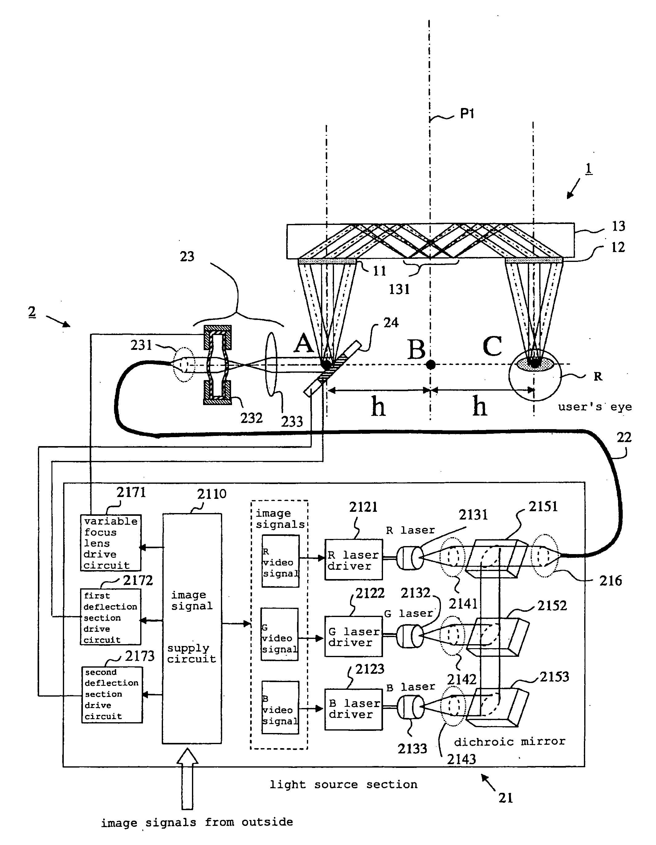
[0030]A retinal scanning display that uses the optical system of the first embodiment of the present invention will be described based on FIG. 1 to FIG. 4.

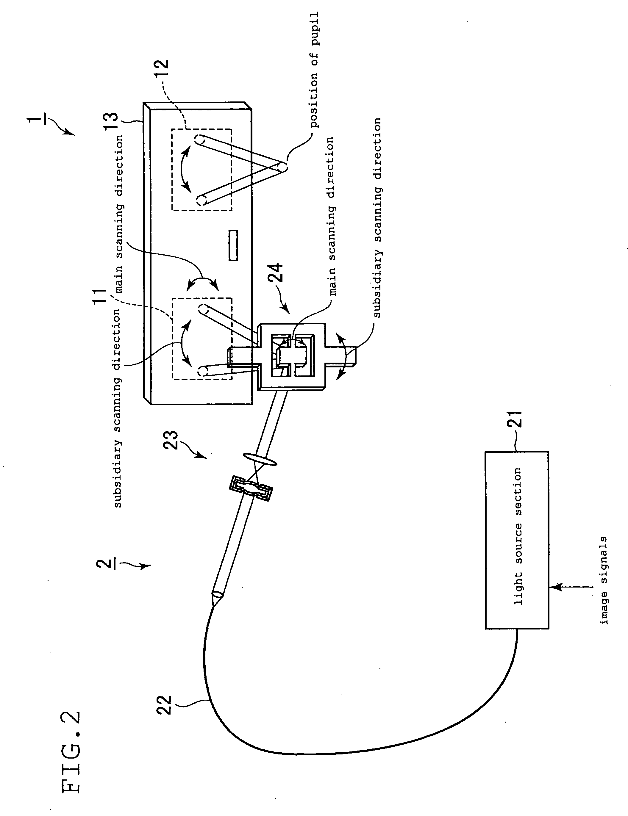
[0031]This retinal scanning display is provided with an optical system 1 and an image forming section 2 as main components.

[0032]The optical system 1 comprises a first diffraction section 11, a second diffraction section 12, and a light guiding section 13. The first diffraction section 11 and the second diffraction section 12 are attached to the light guiding section 13 in a state separated from each other. Centers of the first diffraction section 11 and the second diffraction section 12 are both a distance h from a center of the light guiding sections.

[0033]The first diffraction section 11 diffracts light flux that is incident on this first diffraction section 11 to be incident on the light guiding section 13. As this type of first diffraction section 11, there is, for example, a transmission type d...

applied example

[0055]One example of fitting the device of this embodiment to the head of a user is shown in FIG. 4. With this example, the image forming device 2 is attached to the side of the head of a user, and optical system 1 is arranged in front of the user's face. At this time, the second diffraction section 12 is arranged in front of one eyeball R of the user. In doing this, it is made possible to present a specified image to the user while keeping down constraint of the users field of view.

second embodiment

[0056]Next, an optical system 201 of a second embodiment of the present invention will be described based on FIG. 5. In the description of this embodiment, structural elements that are basically common to the optical system 1 of the first embodiment use the same reference numerals to simplify the following description.

[0057]With the optical system 1 of the first embodiment described above, a transmission type diffraction grating was used as the first diffraction section 11 and the second diffraction section 12. In contrast, in the optical system of the second embodiment a reflection type diffraction grating is used as the first diffraction section 211 and the second diffraction section 212. With this example, the first diffraction section 211 and the second diffraction section 212 are both arranged on the surface of the light guiding section 13, at a side opposite to the eyeball position of the user.

[0058]With the second embodiment also, the first diffraction section 211 and the sec...


PUM


Abstract

The present invention provides an optical system that can reduce the occurrence of aberration, and a scanning retinal display that uses such an optical system. A first diffraction section and the second diffraction section are attached to a light guiding section in a state separated from each other. The first diffraction section diffracts light flux that is incident on it, to be incident on the light guiding section. The light guiding section guides light flux that has been diffracted by the first diffraction section to the second diffraction section using reflection inside the light guiding section. The second diffraction section re-diffracts light flux that has been guided by the light guiding section and output externally of the light guiding section. The first diffraction section, the light guiding section, and the second diffraction section are substantially symmetrical, either side of a virtual plane between the first diffraction section and the second diffraction section.

Description

BACKGROUND OF THE INVENTION[0001]1. Technical Field[0002]The present invention relates to an optical system for light flux transfer, and to a scanning retinal display using such an optical system.[0003]2. Description of the Related Art[0004]An optical system for guiding an image that has been formed on an image display element to the eyes using a diffraction optical system has been proposed, as disclosed in the patent publications.[0005]1) Japanese Unexamined Patent Publication No. 2002-311379[0006]2) Japanese Unexamined Patent Publication No. 2003-140081[0007]3) International Patent publication No. WO2004 / 097498[0008]With this type of optical system, an image is formed at a position that is distance from the eyes, and the formed image can be transferred to the eyes. Accordingly, if this optical system is used it is possible to have an image forming device distant from the eyes. This is effective when, for example, implementing a head mounted display.[0009]However, with the optical ...

Claims


Application Information

Patent Timeline
IPC IPC(8): A61B3/10G02B27/42
CPCG02B6/00G02B6/0026G02B6/005G02B26/106G02B27/0081G02B2027/0174G02B27/42G02B27/4211G02B27/4272G02B27/4294G02B2027/011G02B27/0172
Inventor WATANABE, MITSUYOSHIOKA, HIDENORI
Owner BROTHER KOGYO KK
Why Eureka
Try Eureka