Performance testing apparatus for heat pipes

a technology of performance testing and heat pipes, which is applied in the direction of lighting and heating apparatus, instruments, heat measurement, etc., can solve the problems of inability to precisely reflect the performance of the heat pipe, inability to obtain rth and qmax, and inability to achieve precise heat pipe performan

Inactive Publication Date: 2009-07-30
HON HAI PRECISION IND CO LTD
View PDF16 Cites 11 Cited by
  • Summary
  • Abstract
  • Description
  • Claims
  • Application Information

AI Technical Summary

Benefits of technology

[0012]A performance testing apparatus for heat pipes in accordance with a first embodiment of the present invention comprises a heating set for heating evaporating sections of the heat pipes, a cooling set for cooling condensing sections of the heat pipes, and a supporting set adjustably supporting the heating set and the cooling set thereon. The heating set comprises a first immovable portion and a first movable portion being movable relative to the first immovable portion. Two heating channels are defined between the first immovable portion and the first movable portion for receiving the evaporating sections of the heat pipes, respectively. A temperature sensor is exposed to each of the heating c...

Problems solved by technology

However, Rth and Qmax can not be obtained by this test, and the performance of the heat pipe can not be reflected exactly by this test.
However, in the test, the related testing apparatus has the following drawbacks: a) it is difficult to accurately determine lengths of the evaporating section 2a and the condensing section 2b which are important factors in determining the performance of the heat pipe 2; b) heat transference and temperature measurement ma...

Method used


Image

  • Performance testing apparatus for heat pipes
  • Performance testing apparatus for heat pipes
  • Performance testing apparatus for heat pipes

Examples


Embodiment Construction

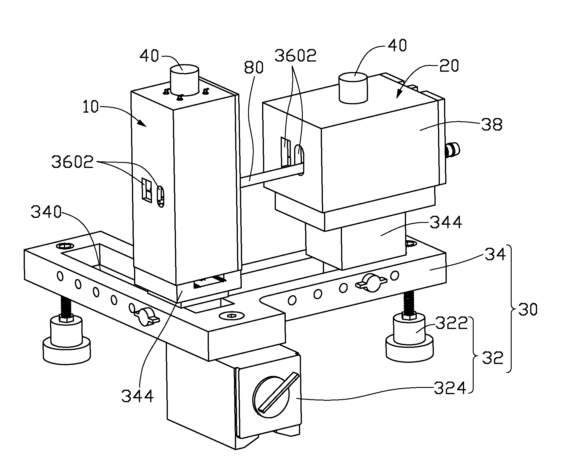
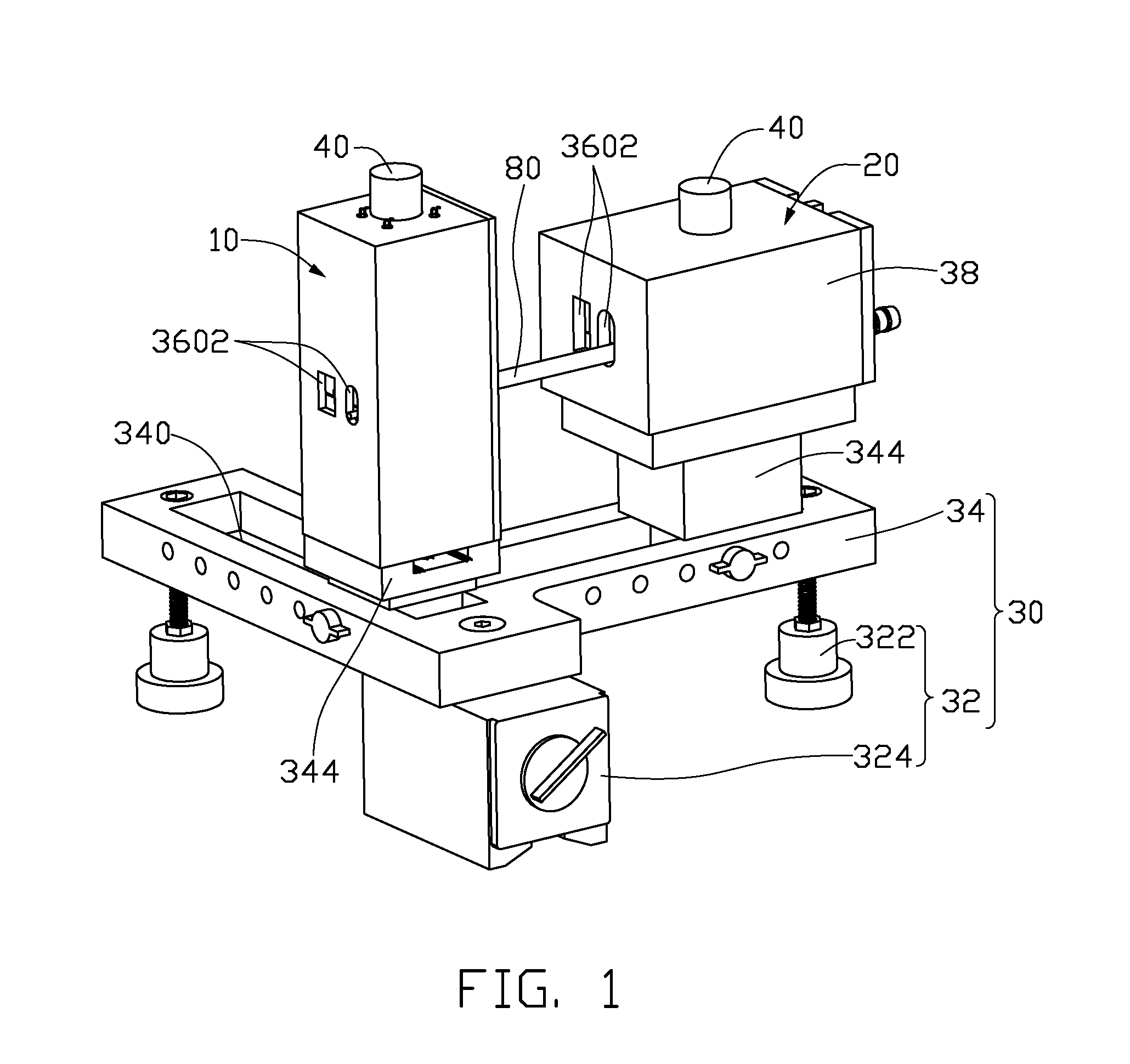
[0022]Referring to FIG. 1, a performance testing apparatus for heat pipes in accordance with a first embodiment of the present invention is shown. The testing apparatus comprises a heating set 10 for heating evaporating sections of a heat pipe 80 and another heat pipe (not shown), a cooling set 20 for cooling condensing sections of the heat pipe 80 and the another heat pipe, and a supporting set 30 supporting the heating set 10 and the cooling set 20 thereon.

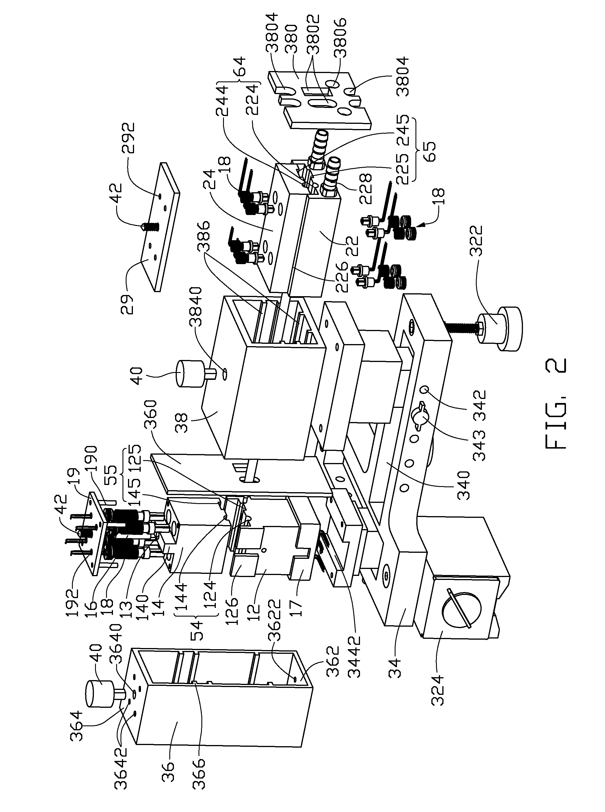
[0023]Referring also to FIG. 2, the heating set 10 comprises a first immovable portion 12 and a first movable portion 14 positioned on the first immovable portion 12. The first movable portion 14 is movable relative to the first immovable portion 12.

[0024]Referring also to FIGS. 3 and 4, the first immovable portion 12 is made of material having good heat conductivity. A first heating member 16 such as an immersion heater, resistance coil, quartz tube and Positive temperature coefficient (PTC) material or the like is embedded in ...


PUM


Abstract

A performance testing apparatus for heat pipes includes a heating set, a cooling set, and a supporting set adjustably supporting the heating and cooling sets thereon. The heating set includes a first immovable portion, a first movable portion and two heating channels therebetween. Temperature sensors are inserted into the first immovable portion and movable portions. Heating members are inserted into the first movable portion and immovable portions. The cooling set includes a second immovable portion, a second movable portion and two cooling channels defined therebetween. Temperature sensors are inserted into the second immovable and movable portions. A cooling passageway is formed in the second immovable portion.

Description

BACKGROUND OF THE INVENTION[0001]1. Field of the Invention[0002]The present invention relates generally to testing apparatuses, and more particularly to a performance testing apparatus for heat pipes.[0003]2. Description of Related Art[0004]It is well known that a heat pipe is generally a vacuum-sealed pipe. A porous wick structure is provided on an inner face of the pipe, and phase changeable working media employed to carry heat is included in the pipe. Generally, according to where the heat is input or output, a heat pipe has three sections, an evaporating section, a condensing section and an adiabatic section between the evaporating section and the condensing section.[0005]In use, the heat pipe transfers heat from one place to another place mainly by exchanging heat through phase change of the working media. Generally, the working media is a liquid such as alcohol or water and so on. When the working media in the evaporating section of the heat pipe is heated up, it evaporates, a...

Claims


Application Information

Patent Timeline
IPC IPC(8): G01K13/00G01M99/00
CPCG01K17/00F28F2200/005
Inventor LIU, TAY-JIAN
Owner HON HAI PRECISION IND CO LTD
Why Eureka
Try Eureka