
MIMO receiver using maximum likelihood detector in combination with qr decomposition

a receiver and maximum likelihood technology, applied in the field of qr decomposition and maximum likelihood detectors, can solve the problems of increasing the number of operations and calculations to decode the symbols represented by vector x, reducing the computational complexity of computing shortest distances, and requiring a lot of effort to transmit and receive data

Active Publication Date: 2009-07-30
QUALCOMM INC
View PDF12 Cites 31 Cited by
  • Summary
  • Abstract
  • Description
  • Claims
  • Application Information

AI Technical Summary

Benefits of technology

This approach significantly reduces computational complexity, enabling faster signal processing, lower hardware requirements, and improved accuracy, allowing for higher data rates and more robust communication systems without compromising precision.

Problems solved by technology

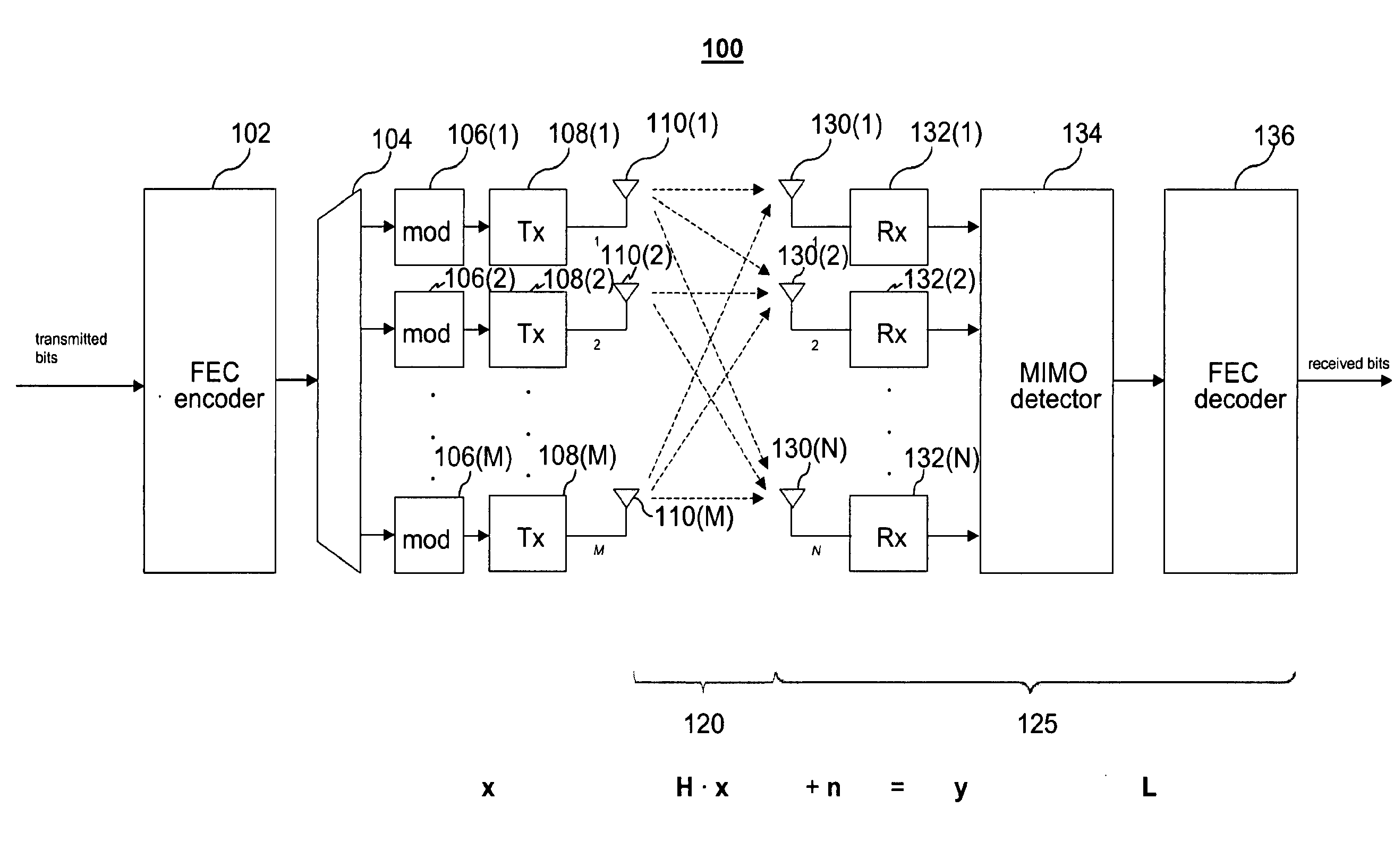
Because wireless networks are expected to operate in unfavorable conditions, such as in the presence of reflections, interference, movement of receivers / transmitters, etc., much effort is needed to correctly transmit and receive data over a wireless channel.
Of course, where there are unrecoverable errors, there is a mismatch between what the sending transmit chain received and what the receiving receive chain outputs.
Thus, computational complexity for determining the most probably transmitted transmit vector grows exponentially (proportional to cM) with the number of transmit antennas (M), thus for larger values of c and M, the number of operations and calculations to decode the symbols represented by the vector x becomes prohibitive.
Again, this can be a difficult computation for some values of c and M.
A MIMO detection process referred to as V-BLAST uses QR decomposition and provides a lower computational complexity than ML detection, but at the price of a lower performance.

Method used


Image

  • MIMO receiver using maximum likelihood detector in combination with qr decomposition
  • MIMO receiver using maximum likelihood detector in combination with qr decomposition
  • MIMO receiver using maximum likelihood detector in combination with qr decomposition

Examples


Embodiment Construction

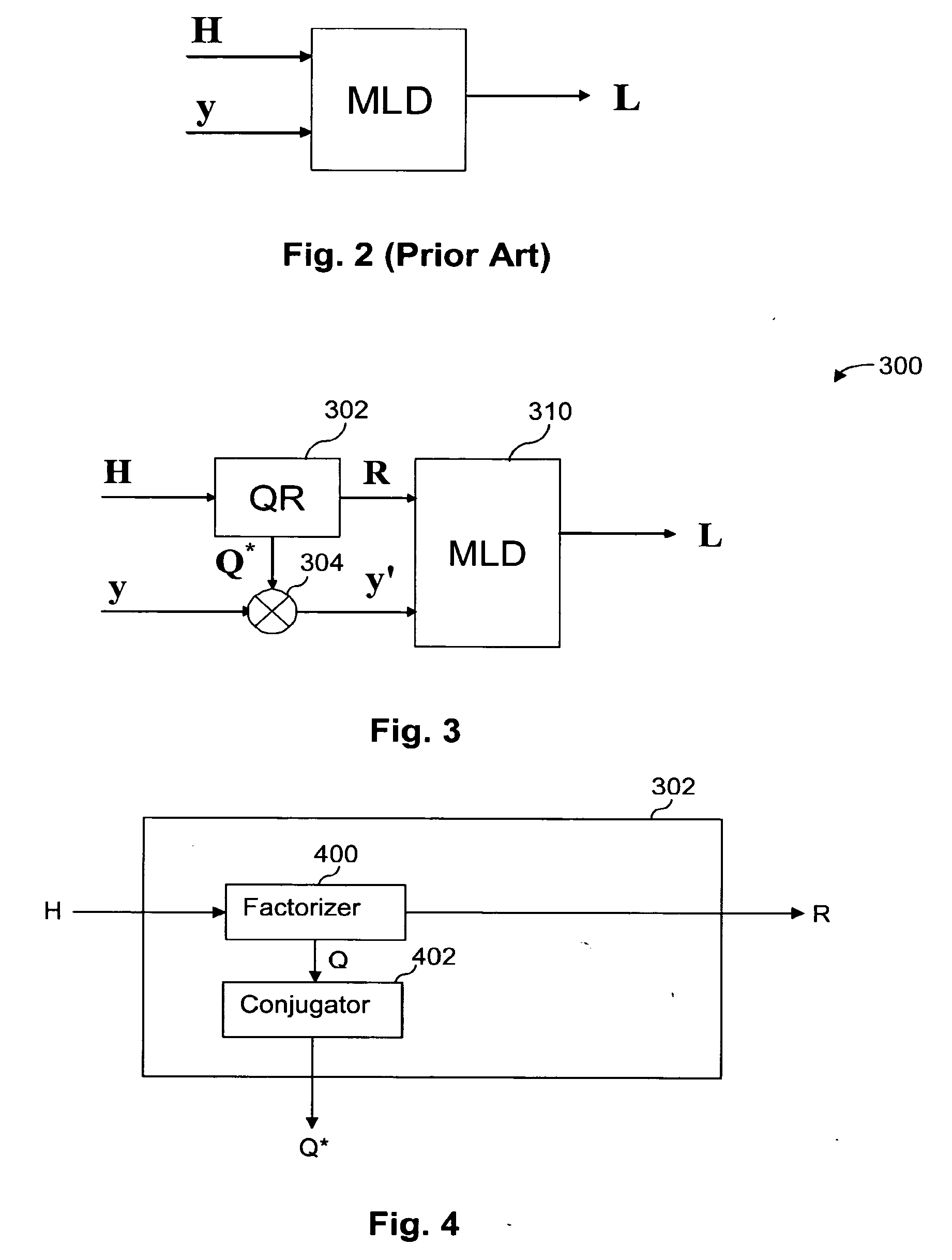
[0049]In embodiments of a receiver according to aspects of the present invention, QR decomposition is used to reduce the number of operations required for detection. As a side effect, some approximations used in computation become less significant, thereby providing higher performance for a given level of precision or comparable performance using lower levels of precision.

[0050]Reducing computational complexity can relieve design constraints and / or allow for improved performance. For example, with reduced computational complexity, received signals can be processed faster for a given amount of hardware thus allowing higher data rates and, for a given data rate, received signals can be processed using less hardware, less power or fewer processing steps. In some instances, computational complexity can be reduced without affecting the resolution of the results, thus not lowering performance. Thus, a savings of computational complexity can be used to provide comparable results more quick...


PUM


Abstract

A MIMO receiver is provided with a preprocessor for performing QR decomposition of a channel matrix H wherein the factored reduced matrix R is used in place of H and Q*y is used in place of the received vector y in a maximum likelihood detector (“MLD”). The maximum likelihood detector might be a hard-decision MLD or a soft-decision MLD. A savings of computational complexity can be used to provide comparable results more quickly, using less circuitry, and / or requiring less consumed energy, or performance can be improved for a fixed amount of time, circuitry and / or energy. Where the MLD uses approximations, such as finite resolution calculations (fixed point or the like) or L1 Norm approximations, the reduced number of operations resulting from using the reduced matrix results in improved approximations as a result of the finite resolution operations. Other methods of reducing the channel matrix might be used for suitable and / or cumulative advantages.

Description

CROSS-REFERENCE TO RELATED APPLICATIONS[0001]This application is a continuation under 35 U.S.C. § 120 of U.S. patent application Ser. No. 11 / 112,068 filed on Apr. 22, 2005 and entitled “MIMO RECEIVER USING MAXIMUM LIKELIHOOD DETECTOR IN COMBINATION WITH QR DECOMPOSITION and claims priority from co-pending U.S. Provisional Patent Application No. 60 / 564,779 filed Apr. 22, 2004 entitled “MIMO RECEIVER USING REDUCED-COMPLEXITY MAXIMUM LIKELIHOOD DETECTOR IN COMBINATION WITH QR DECOMPOSITION.” The entirety of the aforementioned applications are incorporated herein by reference.BACKGROUND OF THE INVENTION[0002]Wireless networks have become increasingly popular, as computers and other devices can be coupled for data communications without requiring wired connections between the network nodes. One set of standards for wireless networks is the IEEE 802.11 standards, but other wireless standards or protocols might be used instead. Because wireless networks are expected to operate in unfavorab...

Claims


Application Information

Patent Timeline
Patent Type & Authority Applications(United States)
IPC IPC(8): H04L5/12H04L27/06
CPCH04L1/06H04L25/0246H04B7/0854H04B7/0413H04B7/0851H04L2025/03426
Inventor AWATER, GEERT A.WONG, BRIAN
Owner QUALCOMM INC
Learn More