Communication system and method using a relay node

a communication system and relay node technology, applied in the field of wireless communication, can solve the problems of signal degradation due to noise and inconvenient degradation of signal quality, and achieve the effect of reducing noise enhancement at the relay nod

Inactive Publication Date: 2006-03-09
NTT DOCOMO INC
View PDF6 Cites 25 Cited by
  • Summary
  • Abstract
  • Description
  • Claims
  • Application Information

AI Technical Summary

Benefits of technology

[0011] The present invention was conceived to overcome the above-described problems, and it is an object of the invention to provide a communication system, a communication node, and a communication method that can prevent degradation of received signal quality at a destination node more efficiently, as compared to conventional techniques, in signal transmission from a source node to the destination.
[0017] With this system, degradation of the received signal quality at the destination node can be prevented more efficiently, as compared with the conventional techniques, in signal transmission from the source node to the destination node using a MIMO multihop scheme.
[0025] With this arrangement, the relaying signal is produced using at least one of the unitary matrices and the transformation matrix, and therefore, multihop transmission can be realized while preventing signal loss and degradation of signal quality.
[0032] With this arrangement, noise enhancement at the relay node can be reduced regardless of the number of relay nodes between the source node and the destination node.

Problems solved by technology

However, since W1 and W2 are inverse matrices of channel matrices H and G, respectively, which are subjected to influence of noise amplitude, signal quality is inevitably degraded.
Accordingly, as the number of hops increases, signal degradation due to the noise become conspicuous.

Method used


Image

  • Communication system and method using a relay node
  • Communication system and method using a relay node
  • Communication system and method using a relay node

Examples


embodiment 1

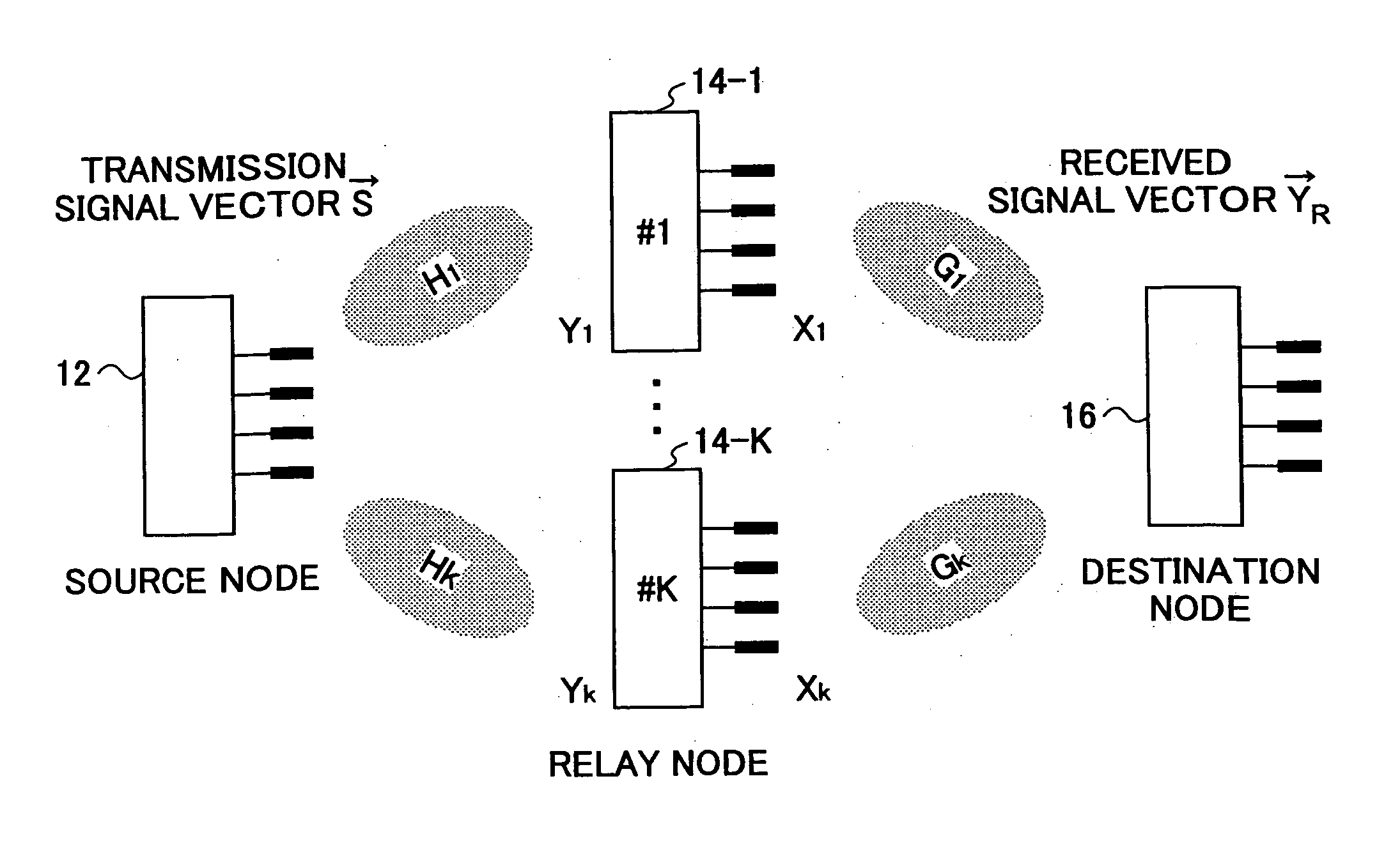
[0053]FIG. 1 is a schematic diagram illustrating the overall structure of a communication system according to an embodiment of the invention. The communication system employs a multihop scheme and a multiple-input multiple-output (MIMO) scheme. The communication system includes a source node 12, a destination node 16, and K (K≧1) relay nodes 14-1 through 14-K. The k-th relay node is denoted as 14-k (1≦k≦K). Communications between the source node 12 and the relay node 14-k and communication between the relay node 14-k and the destination node 16 are performed using a MIMO scheme. Signal transmission from the source node 12 to the destination node 16 is performed by a multihop scheme. In this embodiment, each of the K relay nodes can relay a signal from the source node 12 to the destination node 16 by one hop, for simplification purpose. However, the number of hops may be increased.

[0054] The source node 12 transmits mutually distinguishable signals from multiple antennas (M antennas...

embodiment 2

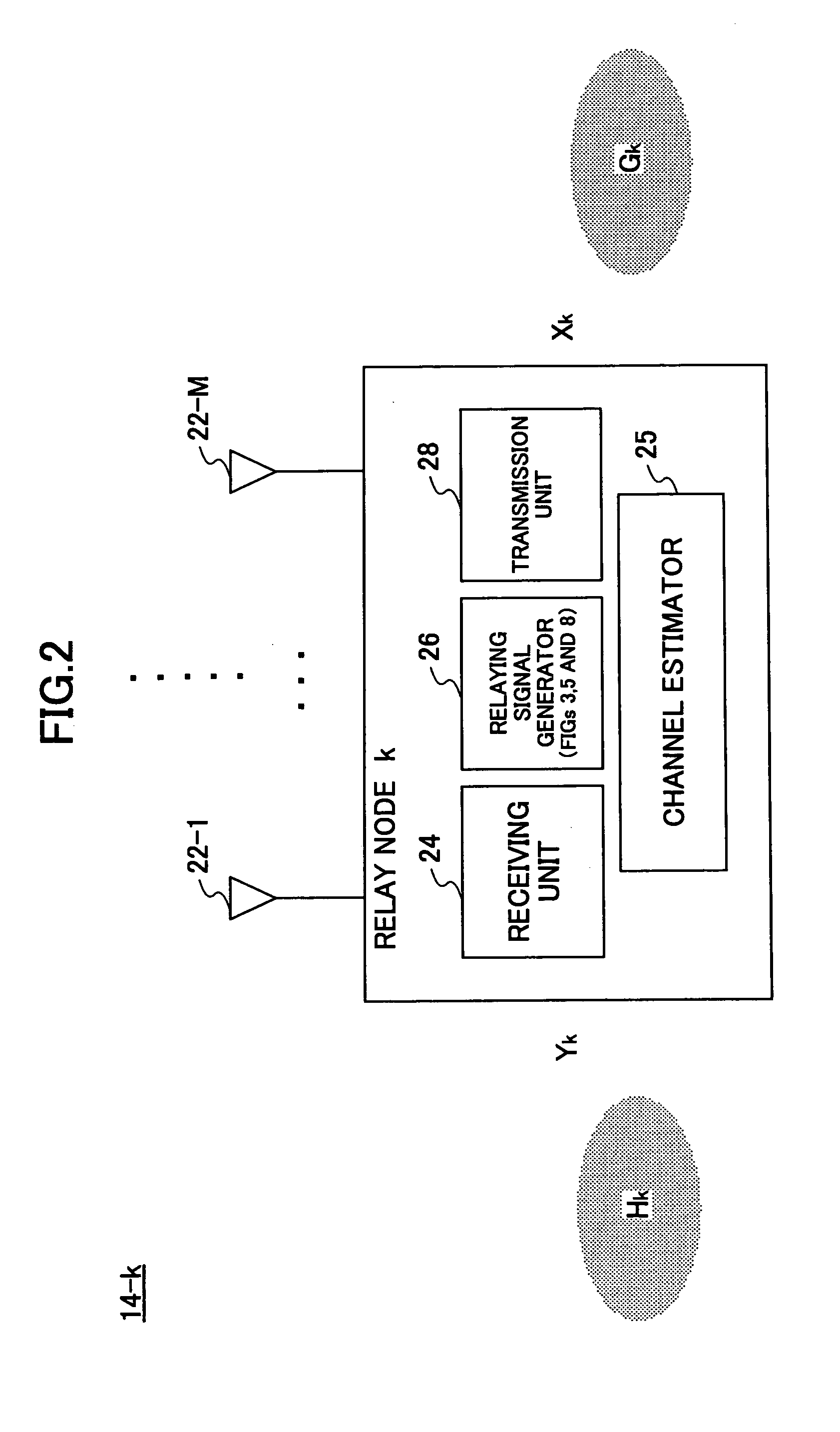
[0082]FIG. 5 is a functional block diagram of the relaying signal generator 26 used in the relay node 14 according to the second embodiment of the invention. The relaying signal generator 26 includes a QR decomposition unit 32, a weighting factor calculation unit 34, a first weighting unit 36, a signal detector 39, and a second weighting unit 62. In the second embodiment, the destination node 16 may have the structure and functions shown in FIG. 5, or alternatively, it may have the structure and functions shown in FIG. 3.

[0083] Upon receiving information about the channel matrices Hk and Gk from the channel estimator 25, the QR decomposition unit 32 breaks down the channel matrix Hk in a form of product of a unitary matrix Qk and a triangular matrix Rk (Hk=QkRk). The the QR decomposition unit 32 also breaks down the channel matrix Gk into the form of a product of a triangular matrix PkH and a unitary matrix OkH (Gk=PkHOkH).

[0084] The weighting factor calculation unit 34 calculates...

embodiment 3

[0101]FIG. 7A and FIG. 7B are graphs showing simulation results of signal transmission according to an embodiment of the invention. The horizontal axis represents power to noise ratio (PNR), and the vertical axis represents capacity. In FIG. 7A, the number of transmission antennas and the number of receiving antennas are each four, and two relay nodes (K=2) are located between the source node and the destination node within a one-hop communication range. The curve of theoretical limit indicates the theoretical limit of the capacity as a function of PNR, and the curve of the prior art indicates the capacity when relaying signals using the zero-forcing method. The curve of Embodiment 1 is obtained by implementing the method of the first embodiment. In FIG. 7B, the number of transmission antennas and the number of receiving antennas are each four, and four relay nodes (K=4) are located between the source node and the destination node within a one-hop communication range. From the graph...


PUM


Abstract

A communication node that relays signals between a source node and a destination node includes (a) a first unitary matrix calculation unit configured to calculate a first unitary matrix based on a first channel between the source node and the relay node, (b) a second unitary matrix calculation unit configured to calculate a second unitary matrix based on a second channel between the relay node and the destination node, (c) a transformation matrix estimation unit configured to estimate a transformation matrix based on a triangular matrix derived from QR decomposition of the first and / or second channel matrix, (d) a relaying signal generator configured to generates a relaying signal by multiplying a received signal by at least one of the first unitary matrix, the second unitary matrix, and the transformation matrix, and (e) a transmission unit configured to transmit the relaying signal to the destination node.

Description

BACKGROUND OF THE INVENITON [0001] 1. Field of the Invention [0002] The present invention generally relates to wireless communications, and more particularly, to a communication node and a communication method using a multihop scheme and a multiple-input multiple-output (MIMO) scheme. [0003] 2. Description of the Related Art [0004] In recent years and continuing, a system based on a combination of a multihop scheme and a MIMO (or multi-antenna) scheme, which system is referred to as a MIMO multihop system, is getting attention. In a multihop scheme, signals are transmitted from a source node to a destination node (or a target node) via one or more relay nodes located between the source and the destination. This system has advantages of expanded coverage by relaying signals, theoretically un-limited signal transmittable areas, and quick establishment of a wireless network. With a MIMO system, multiple transmission antennas and multiple receiving antennas are used to transmit and rece...

Claims


Application Information

Patent Timeline
Patent Type & Authority Applications(United States)
IPC IPC(8): H04L12/28H04J99/00
CPCH04B7/026H04B7/15528H04L1/0618H04L25/0204H04W88/04H04L25/0246H04L25/20H04W52/46H04L25/0228
Inventor SHI, HUIABE, TETSUSHIASAI, TAKAHIROYOSHINO, HITOSHI
Owner NTT DOCOMO INC
Why Eureka
Try Eureka