Maximum likelihood decoding method, equipment, and receiver

a decoding method and probability technology, applied in the field of maximum likelihood decoding process for received signals, can solve the problem of deteriorating quality of estimation solutions, and achieve the effect of improving the quality of estimation solutions and reducing computational complexity

Inactive Publication Date: 2009-04-23
KOKUSA ELECTRIC CO LTD
View PDF3 Cites 28 Cited by
  • Summary
  • Abstract
  • Description
  • Claims
  • Application Information

AI Technical Summary

Benefits of technology

[0025]According to an aspect of this invention, the computational complexity can be reduced by performing the MLD process after each channel matrix is divided into sub-matrices. Further, the MLD process is applied to multiple transmitted signals in each sub-matrix to estimate multiple candidates for the transmitted signals, and hence an effect between transmitted signals is reflected in estimation of the other transmitted signals, thereby improving the quality of an estimation solution.

Problems solved by technology

Accordingly, when multiple candidates for each transmitted signal are individually estimated, effects of other transmitted signals are not reflected, and hence the quality of an estimation solution tends to deteriorate.

Method used


Image

  • Maximum likelihood decoding method, equipment, and receiver
  • Maximum likelihood decoding method, equipment, and receiver
  • Maximum likelihood decoding method, equipment, and receiver

Examples


first embodiment

[0040]A MIMO communication system according to a first embodiment of this invention will be described.

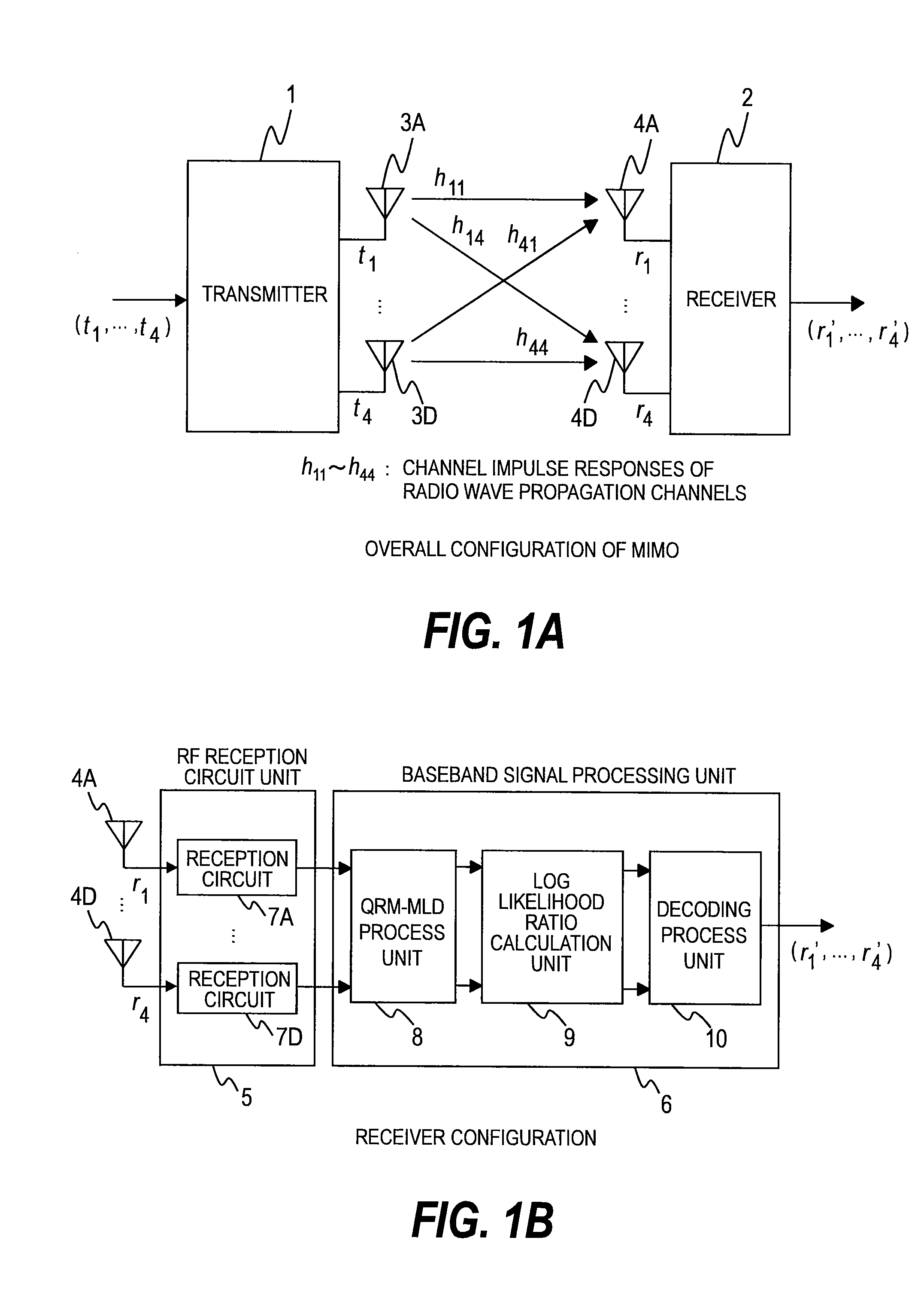
[0041]FIG. 1A is a configuration diagram of the MIMO communication system according to the first embodiment of this invention.

[0042]The MIMO communication system includes a transmitter 1, a receiver 2, transmitter antennas 3 (3A to 3D), and receiver antennas 4 (4A to 4D). Hereinafter, the transmitter antennas 3A to 3D may be collectively referred to as the transmitter antennas 3. The receiver antennas 4A to 4D may also be collectively referred to as the receiver antennas 4.

[0043]The transmitter 1 simultaneously sends transmission data items (t1, t2, t3, t4) in the form of transmitted signals at an identical frequency by using the four different transmitter antennas 3. It should be noted that the transmitted signals are affected by channel impulse responses (h11 to h44) of propagation channels.

[0044]The receiver 2 receives the signals, which have been affected by the channel impulse ...

second embodiment

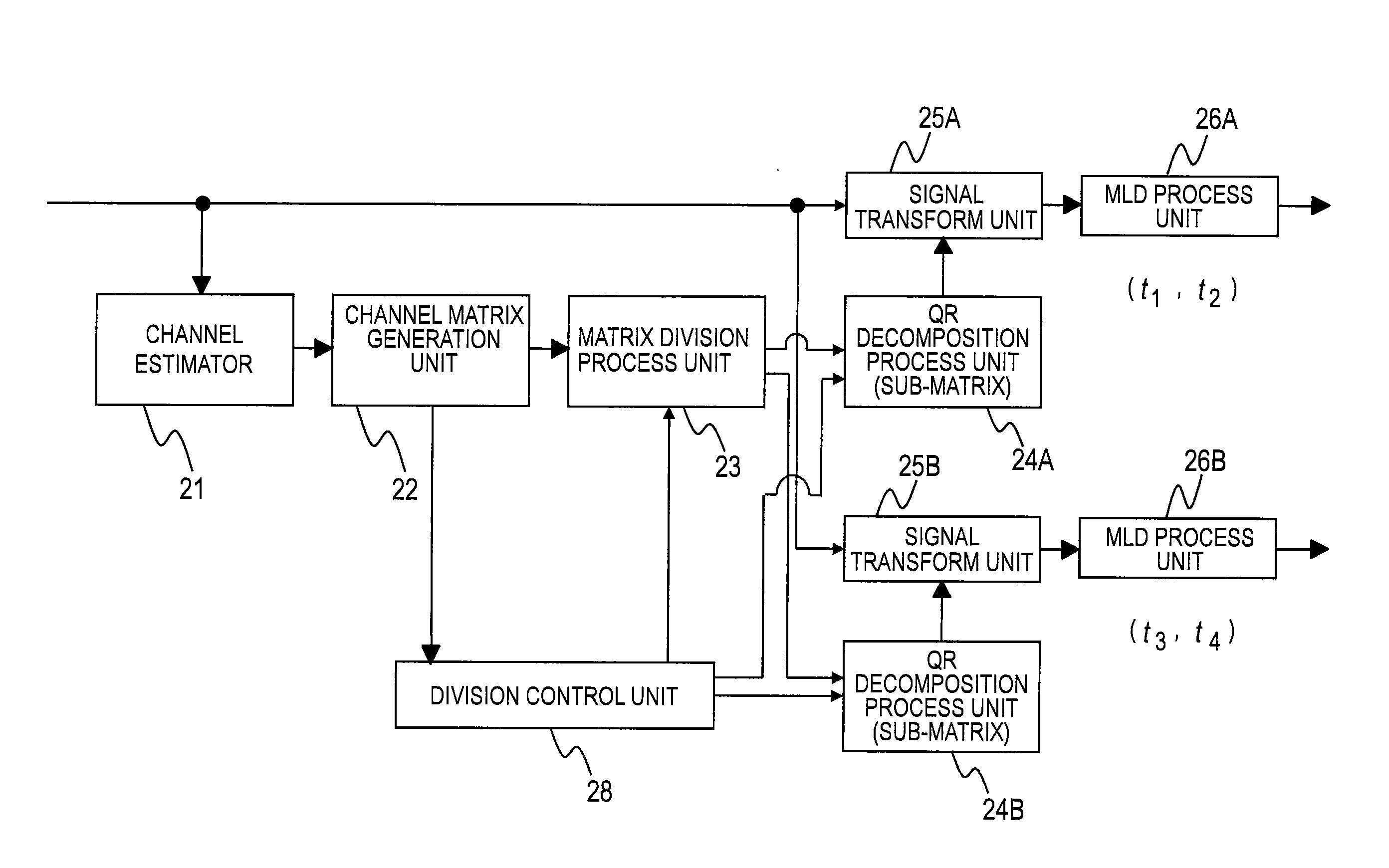
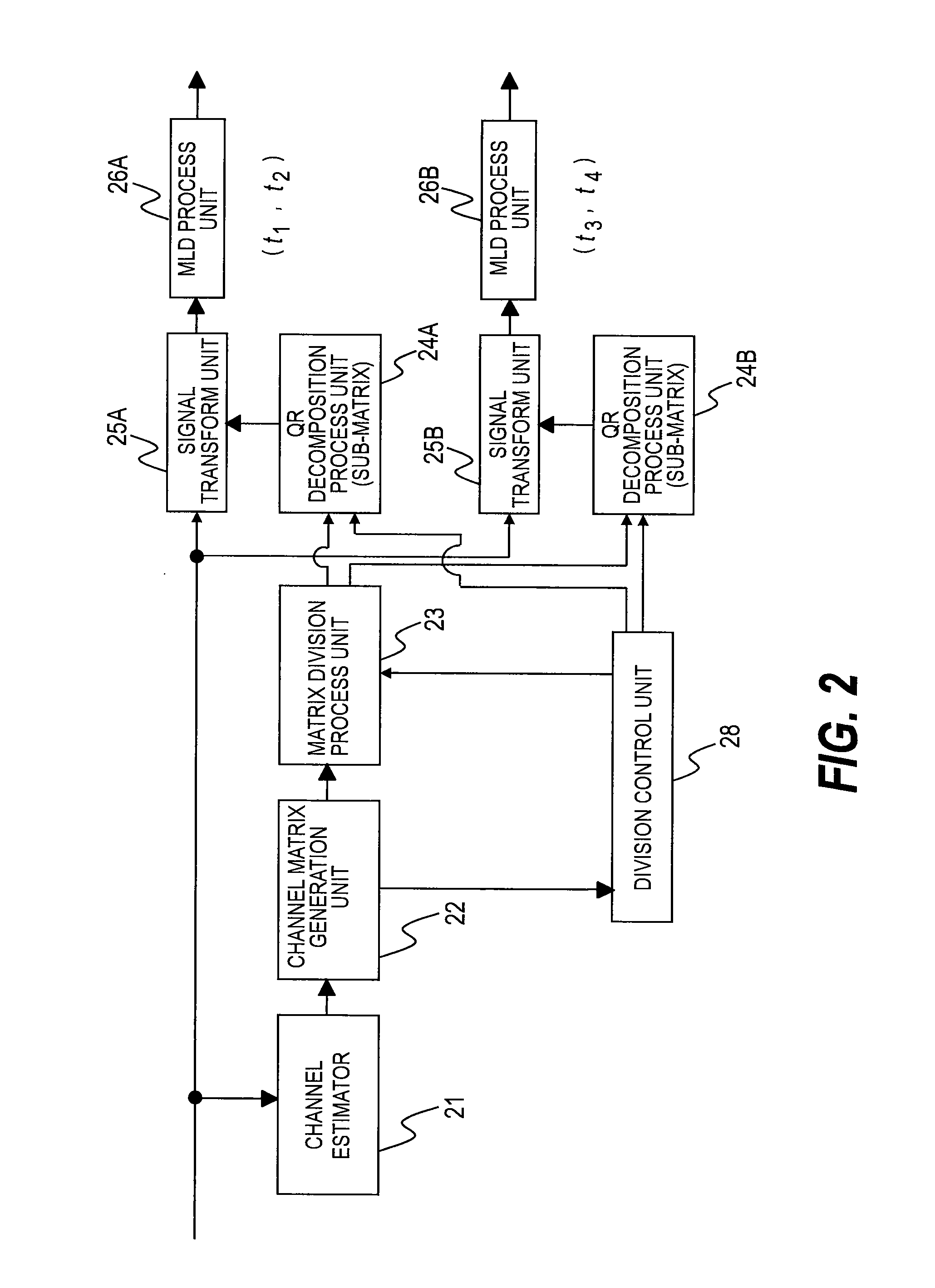
[0088]In a second embodiment of this invention, multiple transmitted-signal estimation solutions are obtained in the first embodiment by applying the MLD process to the sub-matrices, and, in order to improve the quality of a solution, an integrated MLD process is performed by combining the obtained multiple transmitted-signal estimation solutions.

[0089]FIG. 6 is a configuration diagram of a QRM-MLD process unit 8 according to the second embodiment of this invention.

[0090]In the second embodiment, unlike in the first embodiment, the QRM-MLD process unit 8 includes an integrated MLD process unit 27 at a subsequent stage of the MLD process units 26.

[0091]The integrated MLD process unit 27 performs an integrated MLD process by combining transmitted-signal estimation solutions obtained by the MLD process units 26.

[0092]FIG. 7 is a flowchart of a division QRM-MLD process according to the second embodiment of this invention.

[0093]Steps 301 to 304 correspond to the steps 301 to 304 shown in...


PUM


Abstract

Provided is a maximum likelihood decoding method of separating and estimating multiple transmitted signals transmitted by multiple transmitter antennas from multiple received signals received by multiple receiver antennas, comprising: a first step of generating a channel matrix based on channel impulse responses corresponding to the received signals; a second step of dividing the generated channel matrix into multiple sub-matrices, of identifying parts of the received signals corresponding to the sub-matrices obtained through the division, and of transforming the sub-matrices obtained through the division, by using inverse matrices of the sub-matrices obtained through the division; a third step of applying QR decomposition to the transformed sub-matrices to obtain triangular matrices, and of transforming the received signals of the parts by using the obtained triangular matrices; and a fourth step of determining one combination candidate for the parts of the transmitted signals corresponding to the transformed received signals.

Description

CLAIM OF PRIORITY[0001]The present application claims priority from Japanese patent applications JP 2007-272329 filed on Oct. 19, 2007, the content of which is hereby incorporated by reference into this application.BACKGROUND OF THE INVENTION[0002]This invention relates to a wireless communication method and a wireless communication apparatus for stable high-speed communication by using a plurality of transmission and receiver antennas, and more particularly, to a maximum likelihood decoding process for received signals.[0003]A multiple-input multiple-output (MIMO) system in which wireless communication is performed by using a plurality of transmission and receiver antennas achieves a high transmission rate. However, in order to achieve a high transmission rate, it is necessary to accurately separate and detect interferences of a plurality of transmitted signals mixed in received signals therefrom. A maximum likelihood decoding (MLD) method can be used to obtain the most excellent p...

Claims


Application Information

Patent Timeline
Patent Type & Authority Applications(United States)
IPC IPC(8): H04L27/28H04L27/06
CPCH04L25/0206H04L25/0244H04L2025/03426H04L25/03292H04L25/0246H04L25/0204
Inventor MASUI, HIRONARIYANO, TAKASHIKOBAYASHI, TAKEHIKO
Owner KOKUSA ELECTRIC CO LTD
Why Eureka
Try Eureka