Connector

a technology of connecting rods and connectors, applied in the direction of coupling device connections, securing/insulating coupling contact members, electrical devices, etc., can solve the problem of difficult moldability of unitary housings with small locking lances, and achieve the effect of suppressing shaking movements, reducing the effective space of retainers, and sufficient strength

Inactive Publication Date: 2009-07-30
SUMITOMO WIRING SYST LTD
View PDF7 Cites 13 Cited by
  • Summary
  • Abstract
  • Description
  • Claims
  • Application Information

AI Technical Summary

Benefits of technology

[0016]The projection preferably has a cross-shaped cross section and is at or near a central part of the rear surface of the retainer. Thus, a reduction in the effective space of the retainer can be suppressed to a minimum necessary level as compared with the case where the projection is provided over a wide range of the rear surface of the retainer. Further, the cross-shaped cross section ensures sufficient strength for the projection, while also suppressing shaking movements in the height and width directions and hindering pivotal movements of the lance housing about an axis of the projection.

Problems solved by technology

Therefore it is difficult to mold a unitary housing that has small locking lances and the like.

Method used


Image

  • Connector
  • Connector
  • Connector

Examples


Embodiment Construction

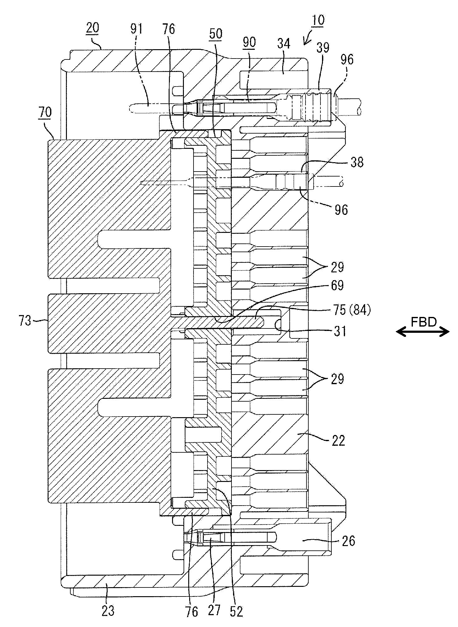
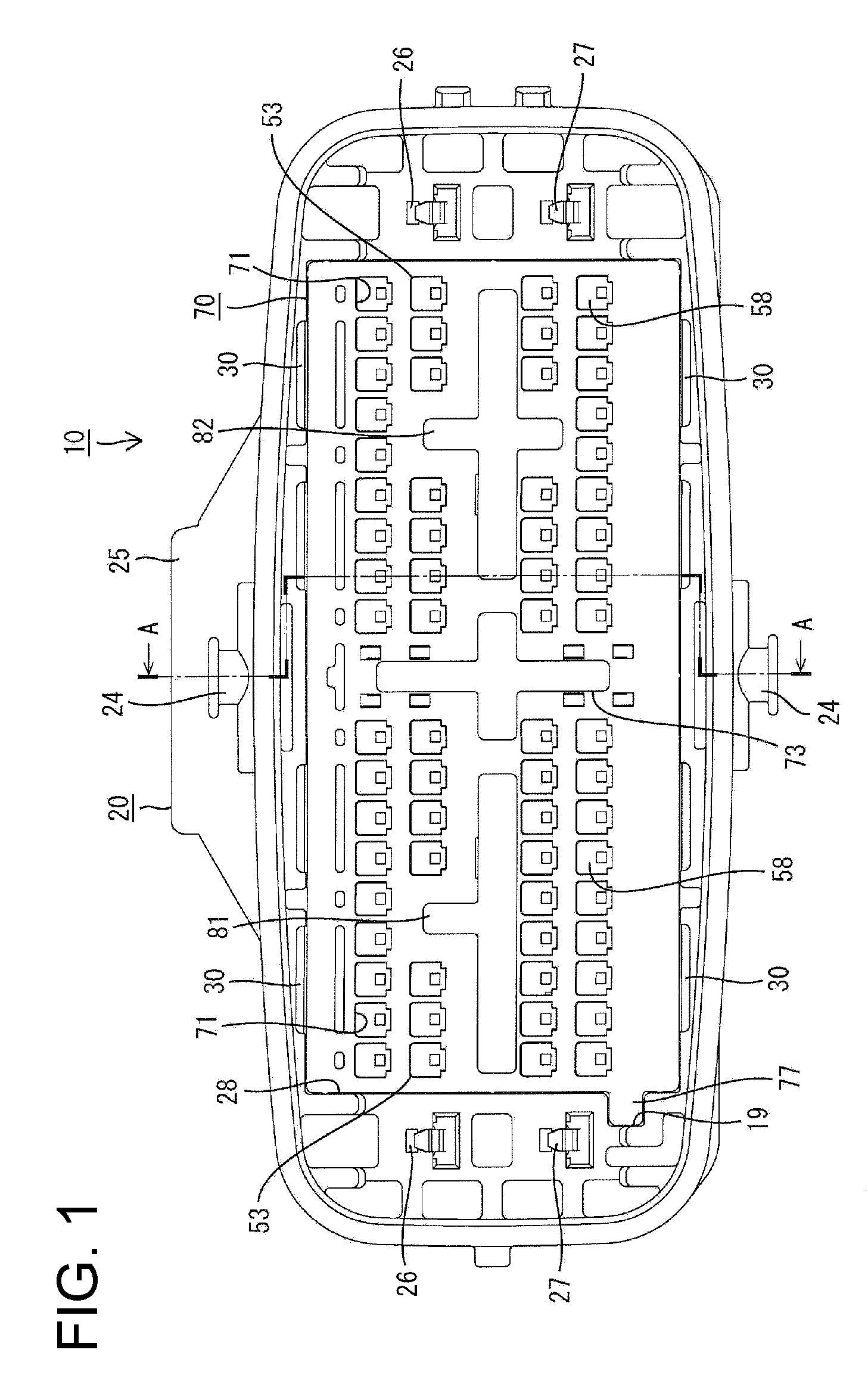
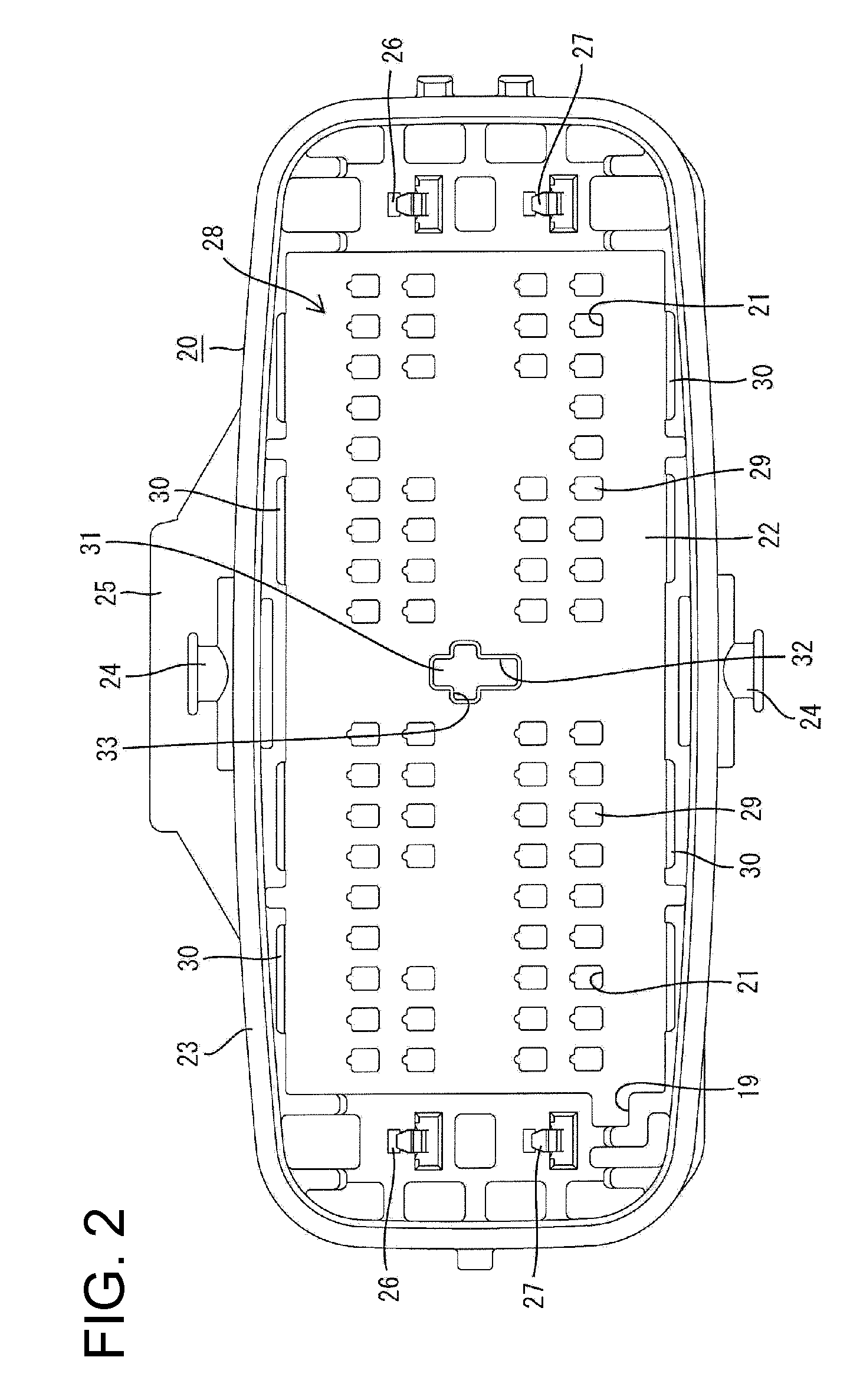
[0035]A male connector in accordance with the invention is illustrated in FIGS. 1 to 17 and is identified generally by the numeral 10. The connector 10 connectable with a mating female connector 100 and is provided with a housing main body 20, a lance housing 50, a retainer 70 and male terminal fittings 90. The housing main body 20, the lance housing 50 and the retainer 70 are made e.g. of a synthetic resin or different synthetic resins and the male terminal fittings 90 are made of an electrically conductive material such as metal. In the following description, an end to be connected with the mating female connector 100 is referred to as the front end concerning forward and backward directions FBD and reference is made to FIG. 1 concerning vertical direction.

[0036]The housing main body 20 cooperates with the lance housing 50 to form a connector housing and includes a terminal accommodating portion 22 formed with cavities 21 for accommodating the respective male terminal fittings 90 ...


PUM


Abstract

In a male connector (10), a lance housing (50) including locking lances (27) is provided separately from a housing main body (20) and a retainer including terminal locking portions (78) to be located in deformation spaces (63) for the locking lances in a properly assembled state is provided separately from the lance housing (50). A projection (75) projects backward from the retainer (70), and a receiving hole (69) for receiving the projection (75) is formed in the front surface of the lance housing (50) to penetrate the lance housing (50). The lance housing (50) is positioned with respect to the retainer (70) by inserting the projection (75) into the receiving hole (69).

Description

BACKGROUND OF THE INVENTION[0001]1. Field of the Invention[0002]The invention relates to a connector.[0003]2. Description of the Related Art[0004]Japanese Unexamined Patent Publication No. H09-161875 discloses a connector that has a housing formed with cavities for receiving terminal fittings. Resiliently deformable locking lances project at inner surfaces of the cavities for locking the terminal fittings in the cavities. A retainer is arranged on the front surface of the housing and has terminal locks that fit into deformation spaces for the locking lances. The terminal locks of the retainer restrict resilient deformations of the locking lances to achieve double locking of the terminal fittings. A guide projects from the front surface of the housing and a fitting portion penetrates the retainer. The guide is inserted into the fitting portion as the retainer is assembled.[0005]Resin flowability decreases during molding a housing for a multipolar connector. Therefore it is difficult ...

Claims


Application Information

Patent Timeline
Patent Type & Authority Applications(United States)
IPC IPC(8): H01R13/627
CPCH01R13/506H01R13/4365
Inventor TANAKA, TSUTOMUMASE, TSUYOSHI
Owner SUMITOMO WIRING SYST LTD
Why Eureka
Try Eureka