Resin pulley

a technology of resin pulleys and pulleys, which is applied in the direction of bearing unit rigid support, gearing, hoisting equipment, etc., can solve the problems of difficult concentration and difficulty in producing evenness on the outer circumferential surface of the outer cylindrical portion during injection molding, and achieve the effect of increasing the roundness of the outer circumferential surface of the resin pulley

Inactive Publication Date: 2009-07-30
JTEKT CORP
View PDF6 Cites 26 Cited by
  • Summary
  • Abstract
  • Description
  • Claims
  • Application Information

AI Technical Summary

Benefits of technology

[0008]The invention has been made in view of the situations described above, and an object thereof is to increase the roundness of the outer circumferential surface of the resin pulley.

Problems solved by technology

According to the configuration described above, since the ribs are provided in such a manner as to be inclined in the circumferential direction relative to the radial imaginary line, the ribs are not in such a state that they project vertically relative to the outer cylindrical portion as with the related art (refer to FIG. 9), and hence, unevenness is made difficult to be produced on the outer circumferential surface of the outer cylindrical portion during injection molding.
In addition, since the ribs are inclined in the circumferential direction relative to the radial imaginary line, when the load from the belt is exerted on the outer cylindrical portion, stress is made difficult to be concentrated on the outer cylindrical portion at the joining portions where the ribs are joined to the outer cylindrical portion, whereby the stress can be dispersed.

Method used


Image

  • Resin pulley
  • Resin pulley
  • Resin pulley

Examples


first embodiment

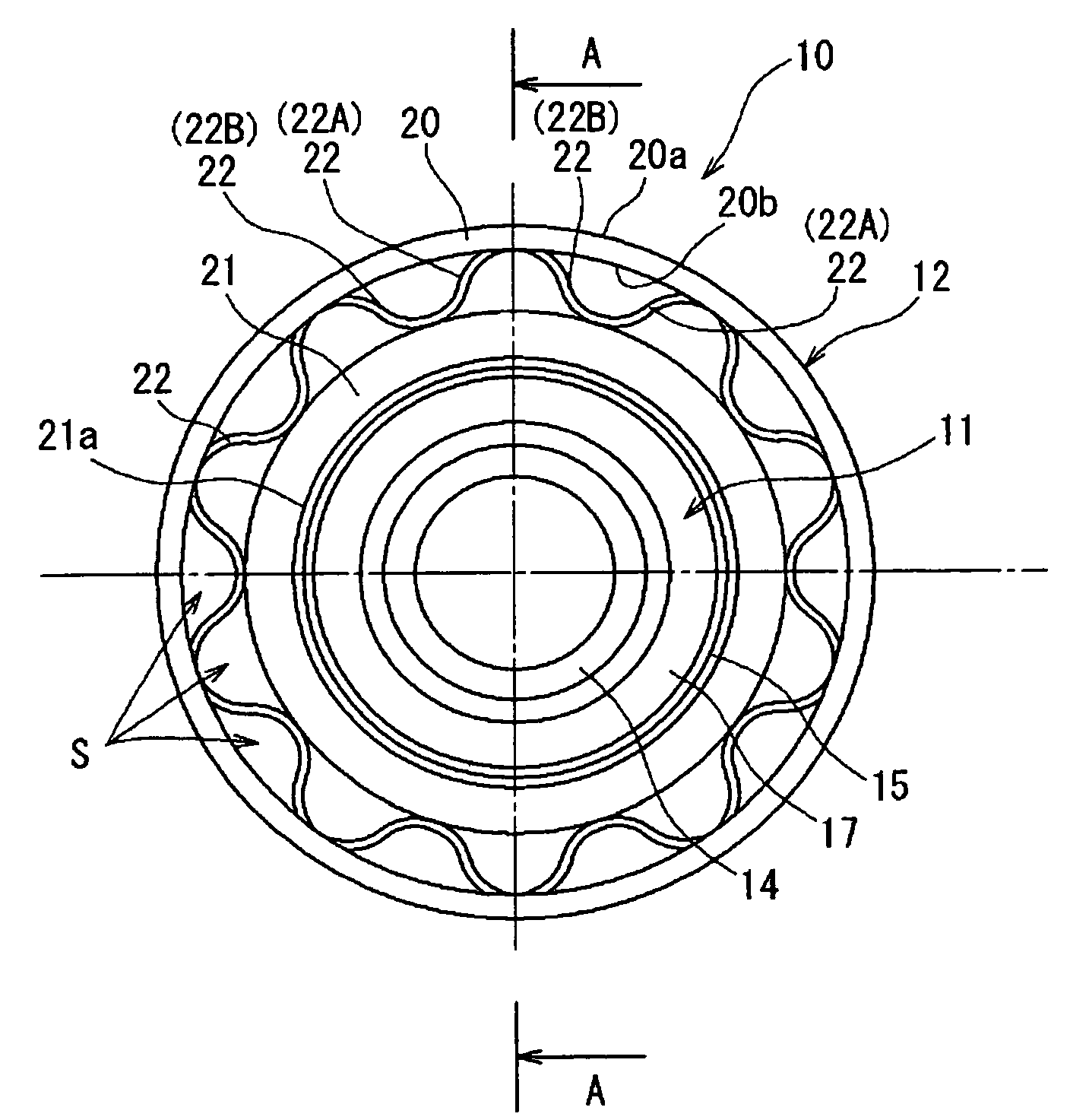
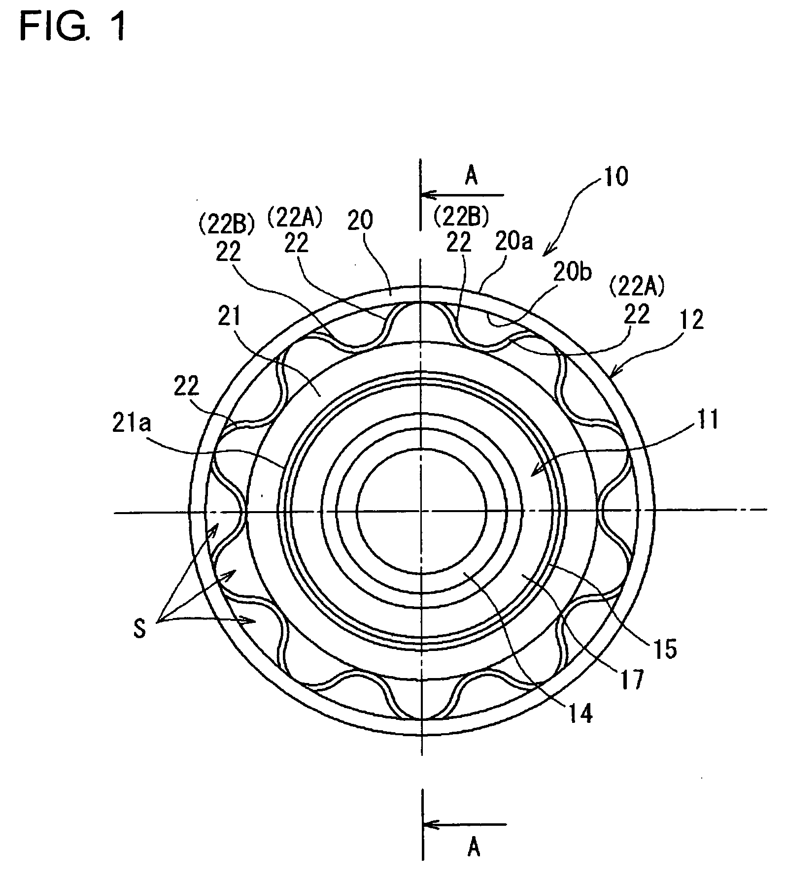
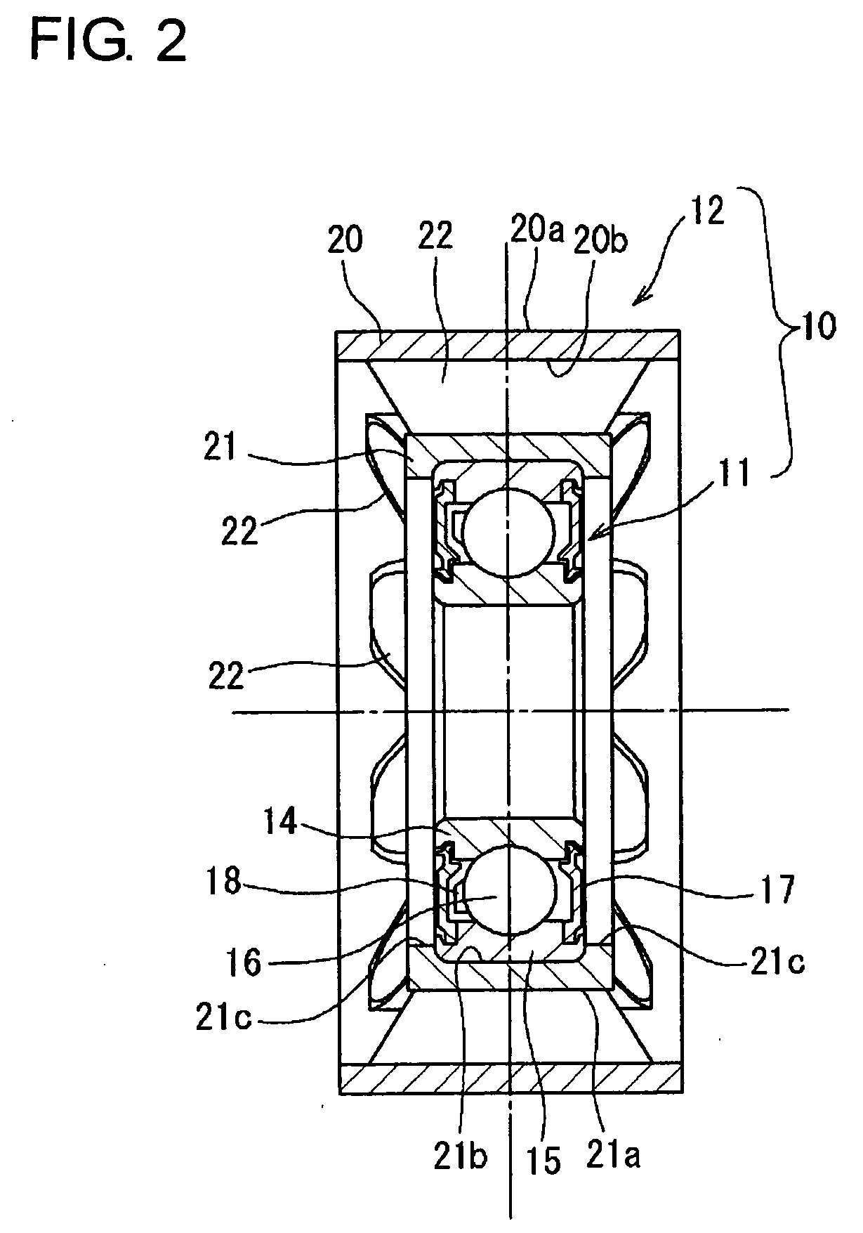
[0026]FIG. 1 is a side view of a resin pulley according to the invention, and FIG. 2 is a sectional view taken along the line A-A and as viewed in a direction indicated by arrows A in FIG. 1. A resin pulley 10 is made up of a rolling bearing 11 and a pulley main body 12. The rolling bearing 11 includes an inner ring 14, an outer ring 15, a plurality of balls (rolling elements) 16 which are disposed rollingly between the inner ring 14 and the outer ring 15, a cage 18 which holds the plurality of balls 16, and seal members 17 which seal tightly a space portion between the inner ring 14 and the outer ring 15. A shaft, not shown, is fitted in an inner circumferential surface of the inner ring 14, and this shaft and the pulley main body 12 are made to rotate relatively via the rolling bearing 11.

[0027]The pulley main body 12 is mounted on an outer circumferential surface of the outer ring 15. The pulley main body 12 includes an inner cylindrical portion 21 whose inner circumferential sur...

second embodiment

[0044]On the other hand, FIG. 6B shows a mold 31 for molding the resin pulley of the second embodiment and this mold is made up of the same upper mold 32 and lower mold 33 as those shown in FIG. 6A. However, the upper mold 32 and the lower mold 33 are superimposed one on the other in such a state that their phases are offset in the circumferential direction. As a result, as is shown in FIG. 5, the rib row 25 made up of the plurality of ribs 23 and the rib row 26 made up of the plurality of ribs 24 are formed between the outer cylindrical portion 20 and the inner cylindrical portion 21.

[0045]In this way, although the resin pulleys of the first and second embodiments are different from each other in arrangement of the ribs 22, 23, 24, the resin pulleys can be molded by the use of the same mold 31, thereby making it possible to reduce the production costs by the use of the common part.

[0046]The applicant of this patent application carried out a test in which a load was applied to the r...


PUM


Abstract

A resin pulley includes: an outer cylindrical portion having an outer circumferential surface on which a belt is to be wound; an inner cylindrical portion which is disposed radially inwards of and concentrically with the outer cylindrical portion; and a plurality of ribs connecting an inner circumferential surface of the outer cylindrical portion and an outer circumferential surface of the inner cylindrical portion. The outer cylindrical portion, the inner cylindrical portion and the ribs are formed integrally from a resin material, and the ribs are provided in such a manner as to be inclined towards a circumferential direction relative to a radial imaginary line as viewed in an axial direction.

Description

BACKGROUND OF THE INVENTION[0001]The present invention relates to a resin pulley which is used as an idler pulley for guiding a belt in a belt transmission system between a crankshaft and an auxiliary in, for example, a motor vehicle engine.[0002]In a motor vehicle, an idler pulley for guising a belt is provided in a belt transmission system which transmits rotational power of an engine to an auxiliary such as an alternator. In recent years, a resin pulley is used for such an idler pulley for reduction in weight and costs (for example, refer to JP-A-7-63249).[0003]FIG. 9A is a side view showing an upper half of a conventional resin pulley, and FIG. 9B is a sectional view taken along the line C-C and as viewed in a direction indicated by arrows C in FIG. 9A. A conventional resin pulley 110 includes an outer cylindrical portion 120 round an outer circumferential surface of which a transmission belt is wound, an inner cylindrical portion which is disposed radially inwards of and concen...

Claims


Application Information

Patent Timeline
Patent Type & Authority Applications(United States)
IPC IPC(8): F16H55/40
CPCF16H7/12F16H2007/0865F16H55/48F16C19/06F16C35/067
Inventor HAMADA, KAZUKIUENO, HIROSHIYANAI, KUNIOSHINOHARA, MASANORIUNO, TOMOKI
Owner JTEKT CORP
Why Eureka
Try Eureka