Control apparatus for transmission

Active Publication Date: 2009-07-30
AISIN SEIKI KK +1
View PDF5 Cites 23 Cited by
  • Summary
  • Abstract
  • Description
  • Claims
  • Application Information

AI Technical Summary

Benefits of technology

[0007]According to an aspect of the present invention, a control apparatus of a transmission for a vehicle, which includes an electric generator provided between an engine and the transmission and regenerating electricity when torque is transmitted from a drive shaft of the vehicle via the transmission in a braking condition, includes a releasing speed measuring unit, an up-shifting operation allowing unit and an up-shifting operation restraining unit. The releasing speed measuring unit measur

Problems solved by technology

Therefore, in a speed-changing period in which a clutch is partially engaged or released until speed changing is completed, torque transmission from the drive shaft to the electric generator may be difficult.
Accordingly, the con

Method used


Image

  • Control apparatus for transmission
  • Control apparatus for transmission
  • Control apparatus for transmission

Examples


Embodiment Construction

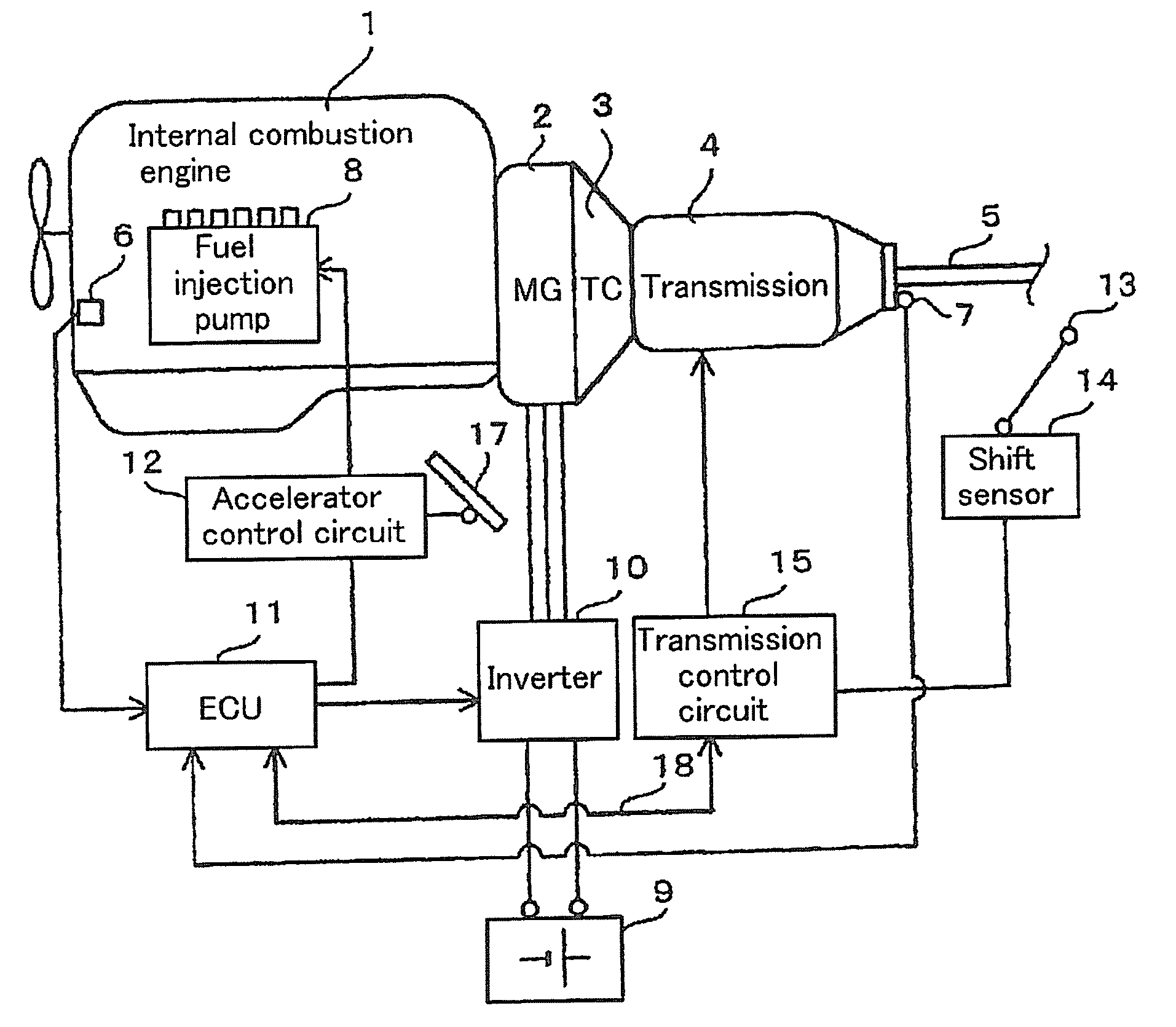
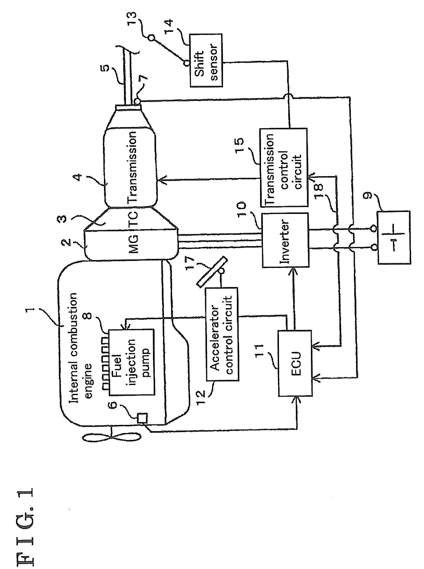
[0014]An embodiment of the present invention will be described hereinafter with reference to the attached drawings. As illustrated in FIG. 1, a system of a vehicle includes an internal combustion engine (hereinafter, referred to as engine) 1, an electric generator (motor generator MG) 2, a transmission 4 and an output shaft 5. The engine 1 and the electric generator 2 are serially connected to each other. The vehicle is driven by the engine I and the electric generator 2 via the transmission 4 and the output shaft 5.

[0015]A diesel engine or a gasoline engine may be employed as the engine 1 as non-limiting examples. An output rotational shaft of the engine 1 is fixedly connected to a rotational shaft of the electric generator 2.

[0016]The electric generator 2 includes a three-phase AC rotary mechanism. A rotational output shaft of the electric generator 2 is connected to an input shaft of the transmission 4 via a torque converter (TC) 3 having a lockup clutch mechanism.

[0017]The trans...


PUM


Abstract

A control apparatus of a transmission for a vehicle, which includes an electric generator provided between an engine and the transmission and regenerating electricity when torque is transmitted from a drive shaft of the vehicle via the transmission in a braking condition, includes a releasing speed measuring unit, an up-shifting operation allowing unit and an up-shifting operation restraining unit. The releasing speed measuring unit measures a releasing speed of an accelerator pedal. The up-shifting operation allowing unit is applied to allow an up-shifting operation under the accelerator pedal being released when a releasing speed of the accelerator pedal is lower than a first threshold value. The up-shifting operation restraining unit is applied to restrain the up-shifting operation under the accelerator pedal being released when the releasing speed of the accelerator pedal is equal to or lower than the first threshold value.

Description

CROSS REFERENCE TO RELATED APPLICATIONS[0001]This application is based on and claims priority under 35 U.S.C. §119 to Japanese Patent Application 2008-017649, filed on Jan. 29, 2008, the entire content of which is incorporated herein by reference.FIELD OF THE INVENTION[0002]The present invention generally relates to a control apparatus for a transmission.BACKGROUND[0003]As an example, JP07-322410A (hereinafter, referred to as reference 1) discloses a vehicle structure including an electric generator for regenerating electricity. According to the reference 1, the electric generator (serving as an auxiliary braking device and an auxiliary driving device) is provided between an internal combustion engine and a transmission (automated transmission). Further, in a condition where torque is transmitted to the electric generator from a drive shaft via the transmission when a braking operation is performed, the electric generator regenerates electricity.[0004]According to the reference 1, i...

Claims


Application Information

Patent Timeline
IPC IPC(8): B60L7/18
CPCB60K6/485Y10T477/65B60W10/115B60W10/196B60W20/00B60W30/18127B60W30/18136B60W50/10B60W2540/106F16H61/0213F16H61/16F16H2059/186F16H2061/0237Y02T10/6226F16H2061/0227F16H2059/183Y10T477/86Y10T477/33Y10T477/692B60W10/10Y02T10/62B60W20/13
Inventor FUTAMURA, SUGURUHOSOYA, RYUTAROSIBATA, SATORU
Owner AISIN SEIKI KK
Why Eureka
Try Eureka