Passive electro-magnetically damped joint

a passive electromagnetic and electromagnetic technology, applied in the field of prosthetics and orthotics, can solve the problems of limited ability to control prosthetics and orthotics joints in a suitable manner for practical clinical application, system is often heavy, bulky, expensive, etc., and achieves the effect of improving cosmetic appearan

Inactive Publication Date: 2009-07-30
ORTHOCARE INNOVATIONS
View PDF3 Cites 74 Cited by
  • Summary
  • Abstract
  • Description
  • Claims
  • Application Information

AI Technical Summary

Benefits of technology

[0029]A further object of the present invention is to provide a new and improved prosthetic or orthotic joint system which provides improved cosmetic appearance.

Problems solved by technology

In the field of prosthetics, there remains a limited ability to control prosthetics and orthotics joints in a suitable manner for practical clinical application.
While many advances are taking place in the field to allow for better prosthetics and orthotics joints that include adaptive control, these systems are often heavy, bulky, expensive, and require significant battery power.
Each of these methods of joint actuation requires significant power consumption to function.
With conventional battery technology, this adds significant weight and size to the system.
Further, because batteries or other electric power storage devices have a limitation in their capacity, there remains a limitation of usable usage time of the system.
This proves to be a limitation in the functional abilities of the orthotic or prosthetic wearer, as charging capabilities are not always accessible.
While this may not be outside of practicality for many individuals, taking a camping trip for instance may not be suitable for an individual using one of these systems.
One challenge that remains with this approach is that the circuit and actuators typically require significantly more power than what energy harvesting devices can offer.
Feedback loop as depicted in the application fails to conceptualize the need for fully assessing the biomechanics of amputee gait, and relies on determining when mutualistic conditions are present to gain energy harvesting from the apparatus, which would not induce increased energy expenditure of the user while the actuator is engaged.
The prior art further fails to embody the inductive brake in a suitable package for clinical prosthetics applications.
The method of packaging the device requires unreasonably large size, and inherently limits the durability and noise abatement potential of the design.
Further, the energy harvester mechanism described in Donelan is tailored to the capture of energy during ambulation, for the purpose of providing power charging to other devices, and does not allow the capabilities of broad joint damping requirements.
A typical trans-femoral amputee for instance ambulating on a damped knee joint can load incredibly significant amounts of torque on the device during ambulatory activities.
Similarly, while the prosthesis is supporting the load of the user, while walking down a hill for instance, it must prevent excessive knee flexion, and can result in over excessive torque / load to be supported by the device.
Mechanical embodiments described in Donelan do not enable for this large range of force damping to occur, and are therefore not suitable for direct control of damped joints in prosthetics or orthotics applications.
In particular the prior art fails to provide controllable prosthetic or orthotic joints that are adaptive in their angle and angular resistance change that are lightweight, small, has an inherently high center of mass, and cosmetic.
Furthermore, the prior art fails to provide a prosthetics or orthotic joint that is inexpensive, is extremely battery efficient, and or does not require battery power at all.
Still further the prior art fails to provide a robotic, animatronic, equipment or similar joint that has similar objectives as for use in prosthetics and orthotics.
Although prosthetic technology has advanced in recent years, the prior art still has failed to bridge the gap between man made prosthetics and user demand and needs.

Method used


Image

  • Passive electro-magnetically damped joint
  • Passive electro-magnetically damped joint
  • Passive electro-magnetically damped joint

Examples


Embodiment Construction

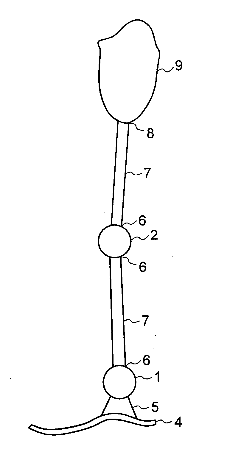
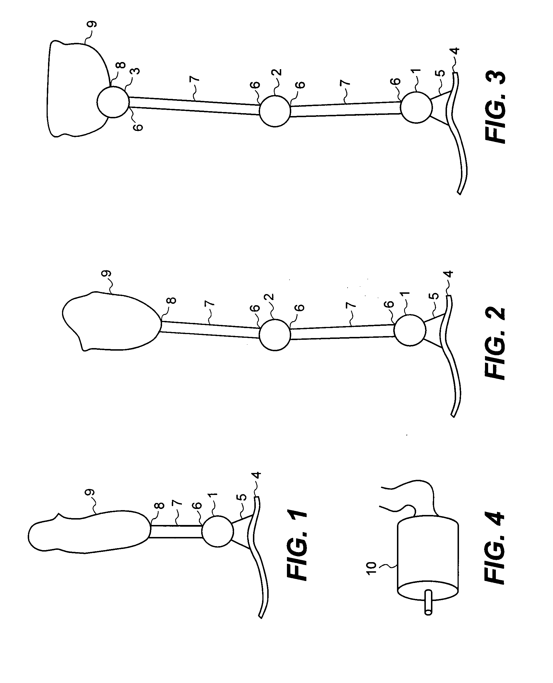
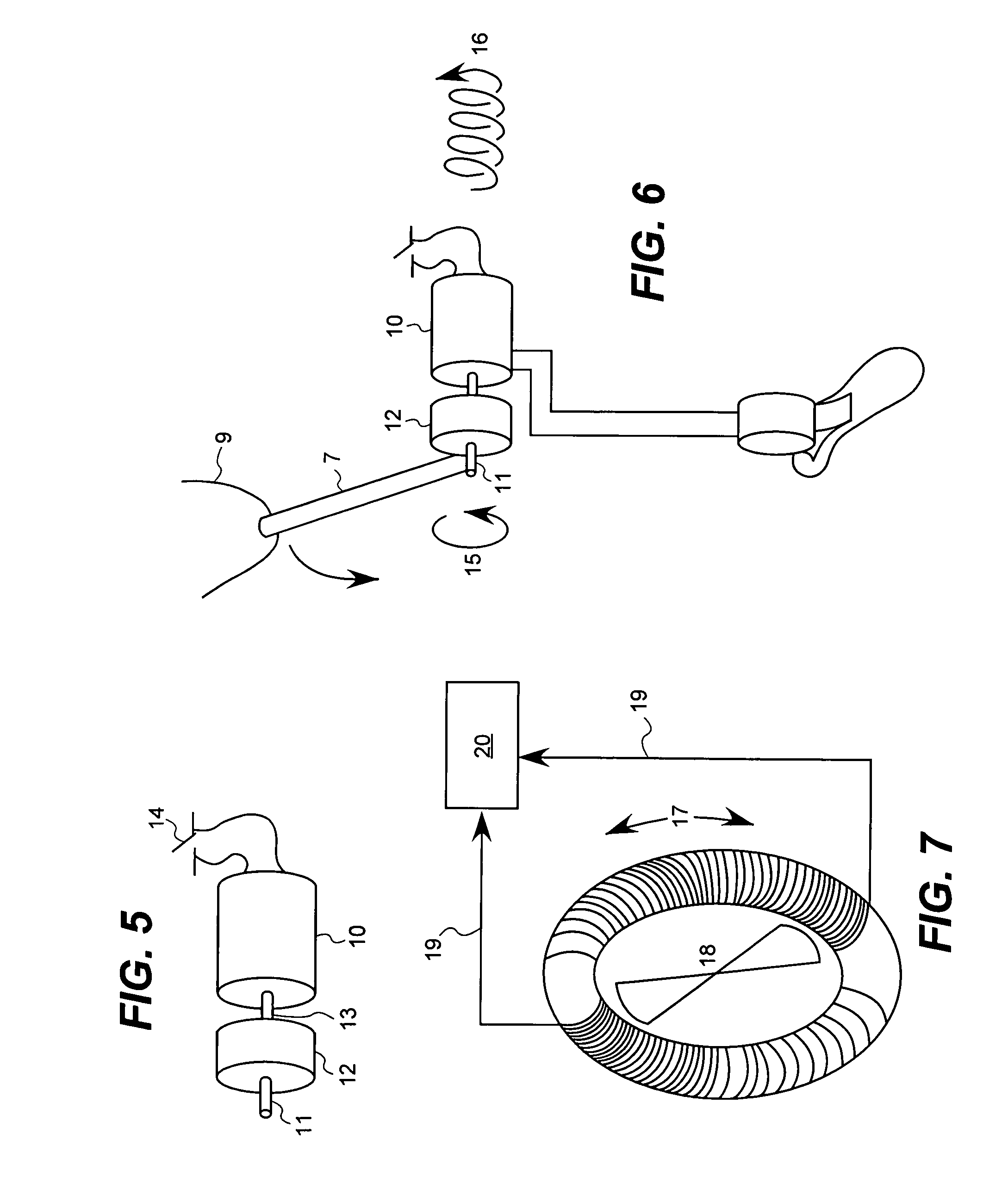
[0068]In a preferred embodiment, the current invention may include the following although it is contemplated that combinations may be utilized to provide a electro-magnetically damped joint design, apparatus, method, and so forth as generally referred to in the application and illustrations described below. It is further contemplated the joint or joint system may be passive, non passive or combinations thereof.

[0069]The current invention joint or joint system may be used as a joint in any type of lower or upper extremity external prosthesis or orthosis (Partial Foot, Symes, Below Knee, Knee Disarticulation, Above Knee, Hip Disarticulation, Hemi-Pelvectomy, Ankle Foot Orthosis—AFO, Knee Orthois—KO, Ankle Foot Knee Orthosis AFKO, etc). The invention may be used as a forefoot joint, ankle joint, knee joint, and / or hip joint, and / or any combination of joints, including upper extremity joints—for joint replacement or joint augmentation.

[0070]It is further contemplated the current inventi...


PUM


Abstract

The present invention comprises an apparatus, system and method utilizing a passive electro-magnetically damped joint for prosthetics or orthotics. Such as system may be controlled through changing the resistive nature of the circuit in which a braking or damping mechanism can sufficiently replicate and augment biomechanical movement. This may be accomplished through electronic circuitry means only, or through the use of intelligent control through a microprocessor and dynamic ambulation replication algorithms.

Description

CROSS-REFERENCE TO RELATED APPLICATIONS[0001]Priority is claimed from provisional patent application U.S. Ser. No. 61 / 004,144, filed on Nov. 23, 2007, and incorporated by reference herein.1. FIELD OF THE INVENTION[0002]The present invention relates generally to prosthetics and orthotics. More particularly, the present invention is a new and improved passive electro-magnetically damped joint.2. DESCRIPTION OF THE KNOWN PRIOR ART[0003]In the field of prosthetics, there remains a limited ability to control prosthetics and orthotics joints in a suitable manner for practical clinical application. While many advances are taking place in the field to allow for better prosthetics and orthotics joints that include adaptive control, these systems are often heavy, bulky, expensive, and require significant battery power. There remains a need for better prosthetics joints that minimize these challenging design aspects.[0004]Conventional approaches for computer enhanced, or computer controlled pr...

Claims


Application Information

Patent Timeline
Patent Type & Authority Applications(United States)
IPC IPC(8): A61F2/30A61F2/48
CPCA61F2/581A61F2002/764A61F2/583A61F2/60A61F2/605A61F2/64A61F2/6607A61F2/68A61F2/72A61F2002/5003A61F2002/6818A61F2002/6836A61F2002/6845A61F2002/701A61F2002/704A61F2002/7625A61F2002/7635A61F2/582A61F2/70
Inventor MARTIN, JAMES JAYSCHULZ, JOELCHAUBEY, PRAVINHASLAM, CRAIG
Owner ORTHOCARE INNOVATIONS
Why Eureka
Try Eureka