Counter control circuit, dynamic reconfigurable circuit, and loop processing control method

a counter control and dynamic reconfigurable circuit technology, applied in program control, computation using denominational number representation, instruments, etc., can solve the problem of especially time-consuming loop control in applications written in c languag

Inactive Publication Date: 2009-07-30
SOCIONEXT INC
View PDF12 Cites 28 Cited by
  • Summary
  • Abstract
  • Description
  • Claims
  • Application Information

AI Technical Summary

Problems solved by technology

At this moment, a loop control is an especially time-consuming control among applications written in C language.

Method used


Image

  • Counter control circuit, dynamic reconfigurable circuit, and loop processing control method
  • Counter control circuit, dynamic reconfigurable circuit, and loop processing control method
  • Counter control circuit, dynamic reconfigurable circuit, and loop processing control method

Examples


example

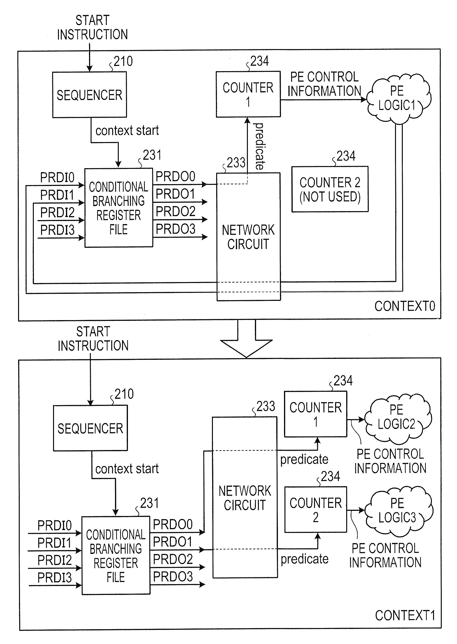
[0078]Next, an example will be described where the reconfigurable circuit is implemented with the context switching operation performed by a source code including the conditional branching processing. FIG. 8 is an example of a source code implementing the context switching in C language. In a source code 800 of FIG. 8, a context 0 portion 810 recites a processing for accumulating and adding input data, and the last portion recites a processing for comparing the accumulated and added value with a fixed value. Context 1 (true / false) portions 820, 830 switch the executed loop control according to the comparison result of context 0. That is, it is required to operate the counter corresponding to a processing of either of the context 1 (true) portion 820 and the context 1 (false) portion 830 according to the comparison result of context 0.

[0079]FIG. 9 is an illustration showing a generation procedure of the conditional branching signal for starting an address counter. FIG. 10 is a block ...


PUM


Abstract

A counter control circuit that controls the operation of a counter arranged in a dynamic reconfigurable circuit executing an arbitrary instruction by dynamically switching an aggregation of reconfigurable processing elements (hereinafter referred to as “PEs”) according to a context reciting a processing content of the PE and a connection content between the PEs, the counter control circuit including: keeping means for keeping an operation instruction signal when the PE executing a conditional branching computation outputs, in a context being adapted to the dynamic reconfigurable circuit, the operation instruction signal of the counter for a subsequent context; output means for outputting the operation instruction signal kept in the keeping means to the counter; and control means for causing the output means to output the operation instruction signal when the context being adapted to the dynamic reconfigurable circuit is switched to the subsequent context.

Description

CROSS-REFERENCE TO RELATED APPLICATIONS[0001]This application is based upon and claims the benefit of priority from the prior Japanese Patent Application No. 2007-337065 filed on Dec. 27, 2007, the entire contents of which are incorporated herein by reference.BACKGROUND[0002]1. Field[0003]Aspects in accordance with the invention relate to a counter control circuit arranged in a dynamic reconfigurable circuit executing an arbitrary processing by dynamically switching an aggregation of reconfigurable processing elements (hereinafter referred to as “PEs”) according to a context reciting a processing content of the PE and a connection content between the PEs, and aspects further relate to a dynamic reconfigurable circuit and a loop processing control method.[0004]2. Description of Related Art[0005]A dynamic reconfigurable circuit (hereinafter referred to as “reconfigurable circuit”) conventionally functions to change an instruction content given to a PE in the reconfigurable circuit and...

Claims


Application Information

Patent Timeline
Patent Type & Authority Applications(United States)
IPC IPC(8): G06F9/38
CPCG06F9/30058G06F9/321G06F9/3842G06F15/7867G06F9/3891G06F9/3897G06F9/3885
Inventor HANAI, TAKASHISUTOU, SHINICHI
Owner SOCIONEXT INC
Why Eureka
Try Eureka